
Scanning mechanism used for optical remote sensing instrument

A scanning mechanism and optical remote sensing technology, applied in the direction of instruments, optics, optical components, etc., can solve the problems of difficult assembly, increased processing and assembly difficulty, complex structure, etc., achieve a large scanning field of view, avoid direct sunlight, and scan fast speed effect

Active Publication Date: 2017-09-08
SHANGHAI INST OF TECHNICAL PHYSICS - CHINESE ACAD OF SCI
View PDF4 Cites 4 Cited by
  • Summary
  • Abstract
  • Description
  • Claims
  • Application Information

AI Technical Summary

Problems solved by technology

The scanning mechanism of Fengyun-2 scanning radiometer has a set of deceleration mechanism, its structure is complex and difficult to assemble
Patent No. Application Publication No. CN103592760A proposes "a high-precision optical scanning mechanism with a large field of view". According to the description in Sections 3 and 4 of its claims, it can be known that a gear reduction mechanism is designed in its structure, and the total reduction ratio of the reducer is 40. :1, increasing the difficulty of processing and assembly

Method used


Image

  • Scanning mechanism used for optical remote sensing instrument
  • Scanning mechanism used for optical remote sensing instrument
  • Scanning mechanism used for optical remote sensing instrument

Examples


Embodiment Construction

[0029] The embodiments of the present invention will be described in detail below in conjunction with the accompanying drawings. This embodiment is implemented on the premise of the technical solution of the present invention, and detailed implementation methods and specific operating procedures are provided, but the scope of protection of the present invention is not limited to the following the described embodiment.

[0030] like figure 1 As shown, the overall structure of the scanning mechanism of this embodiment consists of a scanning mirror assembly 2, a scanning mechanism support 4, a drive shaft assembly 3, a traveling shaft assembly 1, a film support 5, a bracket light shield 6, a shaft light shield 7 and a locking The device protective cover 8 is composed;

[0031] like figure 2 As shown, the scanning mirror assembly 2 includes a scanning mirror 21, a glued bushing 22, a flexible support 23 and a scanning mirror bracket 24. The scanning mirror 21 is supported by a ...


PUM


Abstract

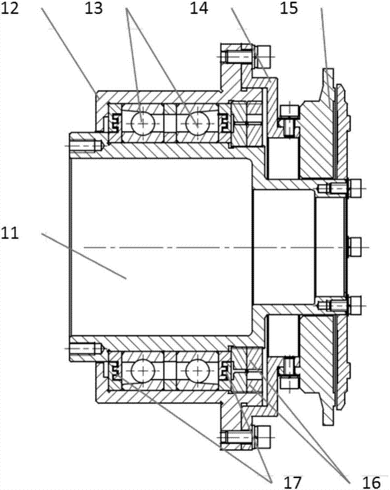
The invention discloses a scanning mechanism used for an optical remote sensing instrument. The scanning mechanism includes a scanning mirror assembly, a scanning mechanism support, a drive shaft assembly, a moving shaft assembly, a thin film support, a support light shade, a shaft light shade and a locking device protecting cover. The scanning mirror assembly includes a scanning mirror, a gluing bush, a flexible support and a scanning mirror support. The moving shaft assembly includes a moving half shaft, in-pair angular contact ball bearings, a switching flange, an electromagnetic locker, a bearing lock nut and a maze seal ring. The drive shaft assembly includes a drive half shaft, in-pair angular contact ball bearings, a bearing seat, a drive motor, a motor housing, a magnetic shielding shade, a round induction synchronizer, a synchronizer protection shade, a bearing locking nut and a maze seal ring. The scanning mechanism is advantaged in that the scanning rate is high and the efficiency is high; the scanning detection field is large; the scanning precision is high; the temperature adaptability is good; the structure is simple; the reliability is improved since direct drive is adopted and use of a speed reduction mechanism with a complex structure is avoided.

Description

technical field [0001] The invention relates to the technical field of motion mechanisms of aerospace optical remote sensing instruments, in particular to a scanning mechanism for optical remote sensing instruments. Background technique [0002] With the development of the aerospace industry, the scanning mechanism of space optical remote sensing instruments has become more and more widely used because it can expand the observation field of view. The existing scanning mechanism adopts an area array detector plus a dual-axis scanning method, which has a long scanning period and low detection efficiency. The Fengyun-2 meteorological satellite takes an image of the Earth every 60 minutes, and the new-generation Fengyun-4 meteorological satellite also needs to take an image every 15 minutes. The scanning mechanism of the Fengyun-2 scanning radiometer has a set of deceleration mechanism, which has a complex structure and is difficult to assemble. Patent No. Application Publicat...

Claims


Application Information

Patent Timeline
Patent Type & Authority Applications(China)
IPC IPC(8): G02B26/10
CPCG02B26/10
Inventor 邓容袁海涛胡亭亮孙胜利
Owner SHANGHAI INST OF TECHNICAL PHYSICS - CHINESE ACAD OF SCI
Learn More