
Optical fiber interference confocal system for on-line inspection of processing quality of optical components

A technology of optical components and processing quality, applied in the field of optical fiber interference confocal systems, can solve the problems of inability to guarantee surface roughness and sub-surface detection, inability to truly evaluate the processing quality of the measured area, and extremely high detection environment requirements. High-resolution confocal microscopy imaging, strong anti-interference ability, simple and compact structure

Active Publication Date: 2019-05-24
苏州菲尔德科技集团有限公司
View PDF4 Cites 0 Cited by
  • Summary
  • Abstract
  • Description
  • Claims
  • Application Information

AI Technical Summary

Problems solved by technology

However, there are still many challenges in the processing quality inspection of large-aperture optical components: 1) The surface roughness and subsurface damage are not detected on the same device, and it is impossible to guarantee the simultaneous detection of surface roughness and subsurface in the same area to be measured, so that The processing quality of the measured area cannot be truly evaluated; 2) The requirements for the detection environment are extremely high, and there are also high requirements for the size of the tested part and the accuracy and stability of its adjustment device, which limits the detection to only It is carried out in a laboratory with good conditions such as vibration, constant temperature and humidity, which greatly reduces the detection efficiency

Method used


Image

  • Optical fiber interference confocal system for on-line inspection of processing quality of optical components

Examples


Embodiment Construction

[0024] The specific embodiments of the present invention will be further described in detail below in conjunction with the accompanying drawings.

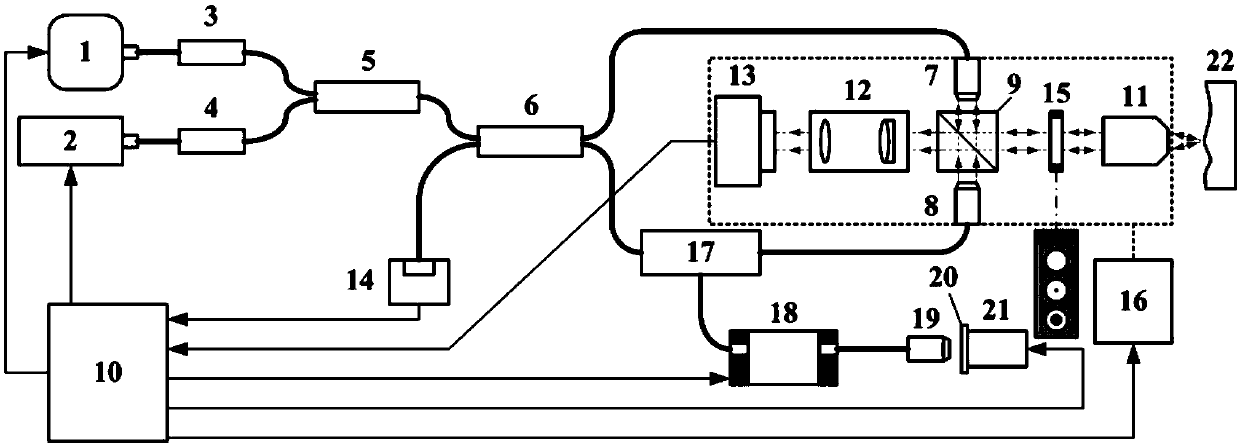
[0025] Such as figure 1 As shown, the optical fiber interference confocal system used for on-line detection of optical element processing quality in the present invention includes a light source switching device, a white light interference device, a laser confocal device, a computer 10, a CCD camera 13 connected to the computer, and a photodetector 14 , five-dimensional motion table 16; wherein, the light source switching device is composed of a broadband light source 1, a laser light source 2, a first fiber isolator 3, a second fiber isolator 4 and a 2×1 fiber coupler 5; the white light interference device adopts Mach- The Zehnder interference structure consists of a 2×2 fiber coupler 6, a first fiber collimator 7, a second fiber collimator 8, a bandwidth splitting prism 9, a fiber circulator 17, an optical delay line 18, and a th...


PUM


Abstract

The present invention discloses an optical fiber interference confocal system used for optical element processing quality online detection. The system adopts an optical fiber device to carry out the common optical path integration on a white light interference system and a laser confocal system to realize the optical element multi-parameter simultaneous online detection, wherein an optical path adjusting method combining the optical delay lines and the piezoelectric ceramics is used to position the interference position rapidly and scan axially, the devices, such as a CCD camera, a porous annulus filter plug-in, etc., are integrated in a measurement probe in a spatial optical path form to realize the white light interference full-field measurement and the laser confocal high-resolution measurement, and the integrated measurement probe is carried on a five-dimension movement bench to realize the high degree of freedom pose adjustment of the measurement probe. The system of the present invention has the characteristics of being small in size, compact in structure and strong in anti-interference capability, etc., the measurement probe and a system main body device are separated, the spatial distance can be adjusted flexibly, the position of a to-be-measured optical element does not need to be adjusted, and the optical fiber interference confocal system has the great advantage for the large-aperture optical element processing quality online detection.

Description

technical field [0001] The invention belongs to the cutting-edge research fields of optics, electronic technology, precision machinery, microscopic photography and the like, and specifically relates to an optical fiber interference confocal system for on-line detection of processing quality of optical elements. Background technique [0002] Large-aperture optical components are of great significance to modern information science. With the continuous development of processing accuracy, the processing accuracy of large-aperture optical components continues to increase, and its shape accuracy needs to be the same as or higher than the light wavelength, and the surface roughness Ra value is less than 1 / 10 of the light wavelength, that is, in the sub- Micron or nanometer level; on the other hand, since the surface parameters of large-aperture optical components are often at the macro scale, this requires the test system to be able to take into account both large-scale and high-pr...

Claims


Application Information

Patent Timeline
Patent Type & Authority Patents(China)
IPC IPC(8): G01B9/02G01B11/24G01B11/30
CPCG01B9/02042G01B11/2441G01B11/30
Inventor 杨树明张国锋薛兴昌杨新宇杨林林
Owner 苏州菲尔德科技集团有限公司
Learn More