
An Inertia-Based Memory Alloy Constrained Isolation Mechanism

A memory alloy and isolation mechanism technology, used in offensive equipment, fuzes, weapon accessories, etc., can solve problems such as unreasonable space utilization, incomplete explosion sequence alignment, and dislocation of isolation mechanisms, so as to reduce accidental detonation and improve isolation. Explosion safety, avoid the effect of incomplete alignment

Active Publication Date: 2018-11-27
湖北三江航天红林探控有限公司
View PDF4 Cites 0 Cited by
  • Summary
  • Abstract
  • Description
  • Claims
  • Application Information

AI Technical Summary

Problems solved by technology

First of all, when the safety of the isolation mechanism is released and the movement is in place, the isolation mechanism does not have a locking function. In the vibration environment, it is easy to cause the isolation mechanism to be misplaced, and eventually lead to incomplete alignment of the explosion sequence; secondly, the two-stage safety of the horizontal rotor type isolation mechanism If the components are misplaced, the size of the mechanism will be larger and the use of space will be unreasonable; again, the horizontal rotor isolation mechanism usually does not effectively use the environmental information on the bomb (such as flight overload, centrifugal force, aerodynamic heat, etc.), and the two-stage insurance The drive needs to consume fuze or bomb power supply, resulting in waste of energy and low safety
The above-mentioned defects limit the application of the horizontal rotor type isolation mechanism to a certain extent, have certain influence on the safety and practicability of the isolation mechanism, and cannot fully satisfy the safe use of the fuze.

Method used


Image

  • An Inertia-Based Memory Alloy Constrained Isolation Mechanism
  • An Inertia-Based Memory Alloy Constrained Isolation Mechanism
  • An Inertia-Based Memory Alloy Constrained Isolation Mechanism

Examples


Embodiment Construction

[0041] In order to make the objectives, technical solutions and advantages of the present invention clearer, the following further describes the present invention in detail with reference to the accompanying drawings and embodiments. It should be understood that the specific embodiments described here are only used to explain the present invention, but not to limit the present invention.

[0042] In addition, the technical features involved in the various embodiments of the present invention described below can be combined with each other as long as they do not conflict with each other.

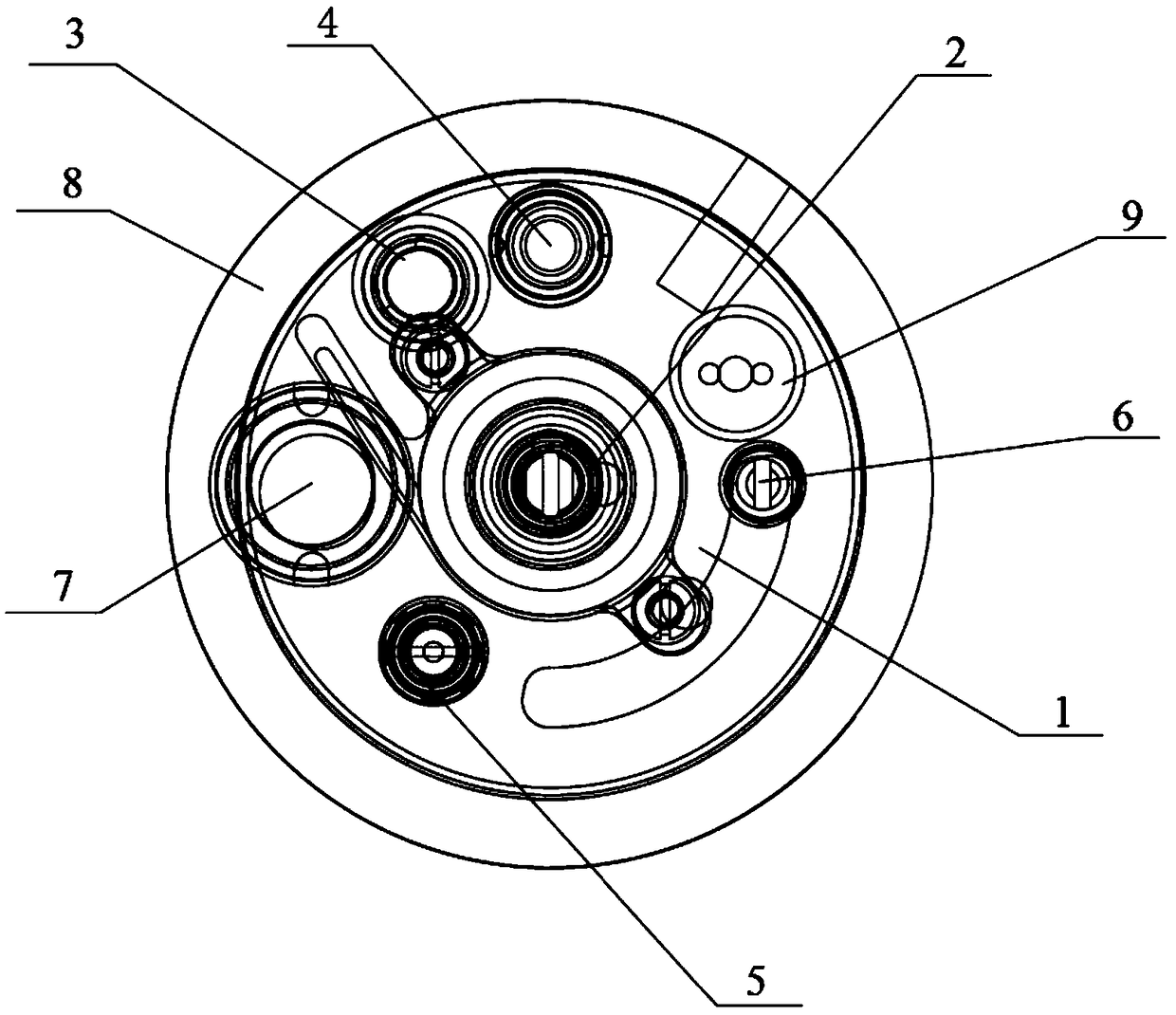
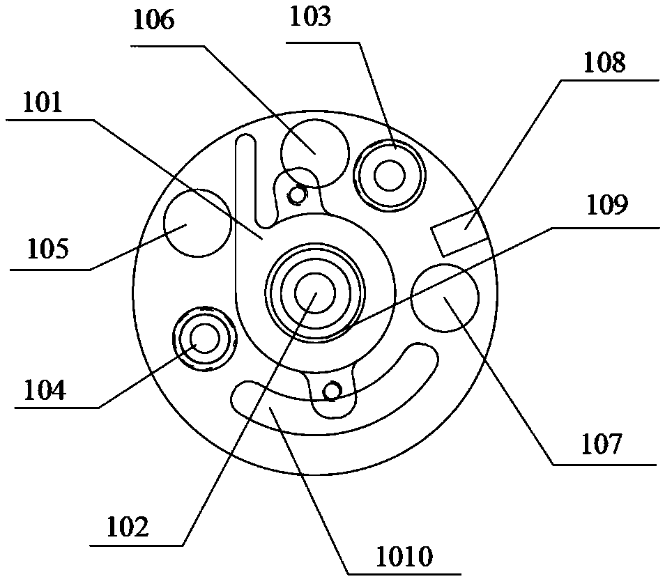
[0043] figure 1 It is a schematic diagram of the overall structure of an inertia-based memory alloy constrained isolation mechanism according to an embodiment of the present invention; figure 2 Is a side view of the rotor structure of the isolation mechanism of the embodiment of the present invention; image 3 It is a front view of the rotor structure of the isolation mechanism of the embodiment o...


PUM


Abstract

The invention discloses an inertia-based memory alloy constrained isolation mechanism, and belongs to the technical field of fuse safety mechanisms. The isolation mechanism comprises a body provided with a rotor hole in the centre, and a rotor coaxially nested in the rotor hole and capable of rotating relative to the body, wherein corresponding holes for accommodating a memory alloy pin puller, an inertia safety component, a fire propagation component and an explosion propagation component are formed in the rotor and the body; and the isolation mechanism has a large isolation termination rotation angle through optimization for the position relationship of the holes, and the isolation mechanism in a safe state and an arming state can be locked at corresponding positions through the arrangement of a multi-stage safety mechanism. According to the isolation mechanism disclosed by the invention, through the abovementioned arrangement, on one hand, the component arrangement form of the isolation mechanism is optimized, the spatial dimensions of the isolation mechanism are reduced, and the applicability of the isolation mechanism is improved; and on the other hand, the safety of the isolation mechanism can be effectively improved through two-stage safety in the safe state, and the alignment of a detonation sequence can be effectively ensured through two-stage locking in the arming state, so that the detonation efficiency is greatly increased.

Description

Technical field [0001] The invention belongs to the technical field of fuze insurance mechanisms, and in particular relates to an inertia-based memory alloy restrained isolation mechanism. Background technique [0002] Pyrotechnics is a general term for disposable components and devices that are loaded with gunpowder or explosives, which burn or explode after being stimulated by the outside to ignite gunpowder, detonate explosives or perform mechanical work. Isolation mechanism is usually set in pyrotechnics, its function is to isolate the sensitive pyrotechnic element in the transmission sequence from the next-level pyrotechnic element at ordinary times, to ensure that the fuze does not ignite when the pyrotechnic product accidentally acts in advance, so as to avoid The ammunition exploded early and endangered the safety of personnel and equipment. [0003] The safety of the fuze involves the entire life cycle of the fuze's demonstration, design, manufacturing, inspection and acc...

Claims


Application Information

Patent Timeline
Patent Type & Authority Patents(China)
IPC IPC(8): F42C15/24F42C15/21
CPCF42C15/21F42C15/24
Inventor 李响李晓张俊
Owner 湖北三江航天红林探控有限公司
Learn More