
Self-propelled tunnel lining concrete curing stand

A self-propelled concrete technology, which is applied in the direction of tunnel lining, tunnel, shaft lining, etc., can solve the problems of endangering driving safety, inconvenient maintenance operations, and large working pressure of the bench, so as to reduce costs, improve convenience, and ensure efficiency. Effect

Active Publication Date: 2017-09-08
江苏钦宇建设工程有限公司
View PDF15 Cites 17 Cited by
  • Summary
  • Abstract
  • Description
  • Claims
  • Application Information

AI Technical Summary

Problems solved by technology

[0002] In the tunnel engineering, affected by the wind tunnel effect, the tunnel lining concrete will bear greater pressure. The faster the vehicle travels, the greater the pressure will be. For high-speed railway tunnels, in order to ensure driving safety, the surface of the tunnel lining structure The strength of the concrete must be qualified, and no slag or blocks should be dropped when the vehicle is passing, which will endanger the driving safety. After the concrete lining is poured and the formwork is removed, if the maintenance is not carried out in time, the water in the concrete surface will evaporate and lose quickly, resulting in the dehydration of the concrete surface, and the cement will not be sufficient. Hydration, the color of the concrete surface turns white, flakes or powder falls off, and the strength of the concrete does not meet the design requirements. Therefore, after the tunnel lining concrete is poured, it must be fully cured to ensure the strength and durability of the lining concrete. However, the current maintenance equipment can only adapt to one type of tunnel operation, and cannot be adjusted according to the height and width of the tunnel. Moreover, when the maintenance of the whole tunnel is carried out at the same time, it will cause a large working pressure on the bench. , requires overall maintenance, which not only causes waste of equipment resources, but also increases the difficulty of maintenance, resulting in very inconvenient maintenance operations

Method used


Image

  • Self-propelled tunnel lining concrete curing stand
  • Self-propelled tunnel lining concrete curing stand
  • Self-propelled tunnel lining concrete curing stand

Examples


Embodiment Construction

[0015] The following will clearly and completely describe the technical solutions in the embodiments of the present invention with reference to the accompanying drawings in the embodiments of the present invention. Obviously, the described embodiments are only some, not all, embodiments of the present invention. Based on the embodiments of the present invention, all other embodiments obtained by persons of ordinary skill in the art without making creative efforts belong to the protection scope of the present invention.

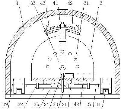
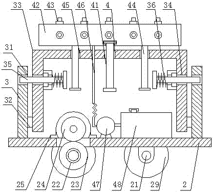
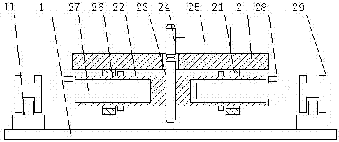
[0016] see Figure 1-4 , the present invention provides a technical solution: a self-propelled tunnel lining concrete maintenance platform, comprising a tunnel body 1 and a platform 2, rails 11 are fixedly installed on both sides of the inner bottom surface of the tunnel body 1, and the lower surface of the platform 2 passes through The support base 21 is rotatably connected with a rotating shaft 22, the center of the outer surface of the rotating shaft 22 is ...


PUM


Abstract

The invention discloses a self-propelled tunnel lining concrete curing stand. The stand comprises a tunnel body and a stand, rails are fixedly mounted on two sides of the bottom face in the tunnel body, and a rotation shaft is rotatably connected to the lower surface of the stand through a supporting base; a driven gear is fixedly connected to the center of the outer surface of the rotation shaft, a driving gear is meshed to the upper surface of the driven gear, and a gear motor is fixedly connected to the driving gear through a shaft; the gear motor is fixedly mounted on the upper surface of the stand, oblate holes are formed in the side faces of two ends of the rotation shaft, and an oblate shaft is connected in the oblate holes in a sliding mode; a positioning nut is connected to the outer surface of the oblate shaft in a threaded mode, idler wheels are fixedly connected to two ends of the oblate shaft, and the idler wheels are fixedly connected to the upper surfaces of the rails. The self-propelled tunnel lining concrete curing stand can improve the convenience of concrete curing greatly, guarantee the efficiency of concrete curing and lower costs.

Description

technical field [0001] The invention relates to the technical field of tunnel engineering, in particular to a self-propelled tunnel lining concrete maintenance platform. Background technique [0002] In the tunnel engineering, affected by the wind tunnel effect, the tunnel lining concrete will bear greater pressure. The faster the vehicle travels, the greater the pressure will be. For high-speed railway tunnels, in order to ensure driving safety, the surface of the tunnel lining structure The strength of the concrete must be qualified, and no slag or blocks should be dropped when the vehicle is passing, which will endanger the driving safety. After the concrete lining is poured and the formwork is removed, if the maintenance is not carried out in time, the water in the concrete surface will evaporate and lose quickly, resulting in the dehydration of the concrete surface, and the cement will not be sufficient. Hydration, the color of the concrete surface turns white, flakes o...

Claims


Application Information

Patent Timeline
Patent Type & Authority Applications(China)
IPC IPC(8): E21D11/10
CPCE21D11/102Y02E10/20
Inventor 靳云帆
Owner 江苏钦宇建设工程有限公司
Learn More