


Quick Research
Generate reliable direction feasibility study reports for your R&D in just a few steps.

Technical Q&A
Discover and master advanced knowledge NOW. Basics, ideas, possibilities, all at once.

Find Solutions
As an expert in R&D theories, this can generate solutions to your technical problems instantly.

Evaluate Feasibility
Analyze your overall solution with one click, know your potential R&D risks in advance.

Monitor Landscape
Get weekly tech updates, stay abreast of the latest tech innovations and key insights.
Fully hidden door stop
A concealed, door stop technology, applied in construction, building fastening devices, wing leaf fastening devices, etc., can solve problems such as poor safety, reduce production costs, have broad market application prospects, and fast and convenient installation Effect
- Summary
- Abstract
- Description
- Claims
- Application Information
AI Technical Summary
Problems solved by technology
Method used
Image

Examples
Embodiment 1
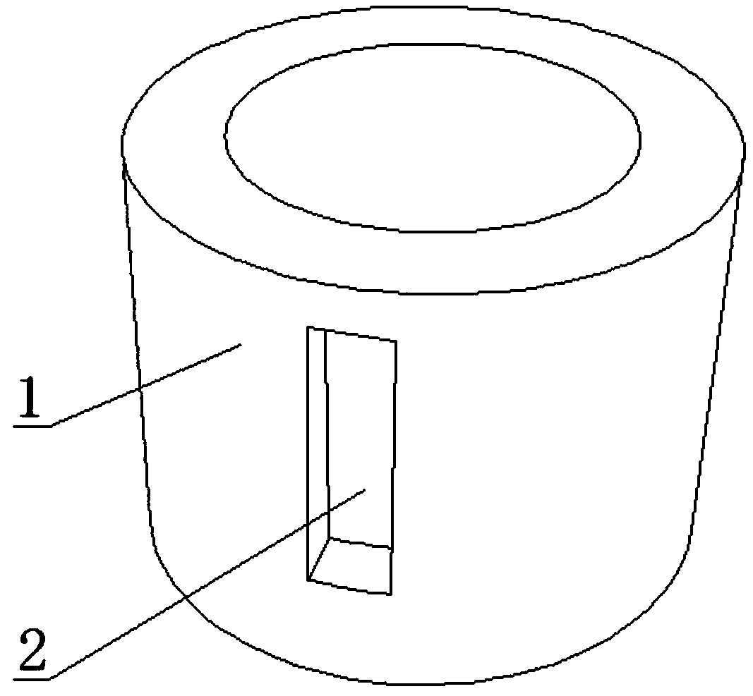
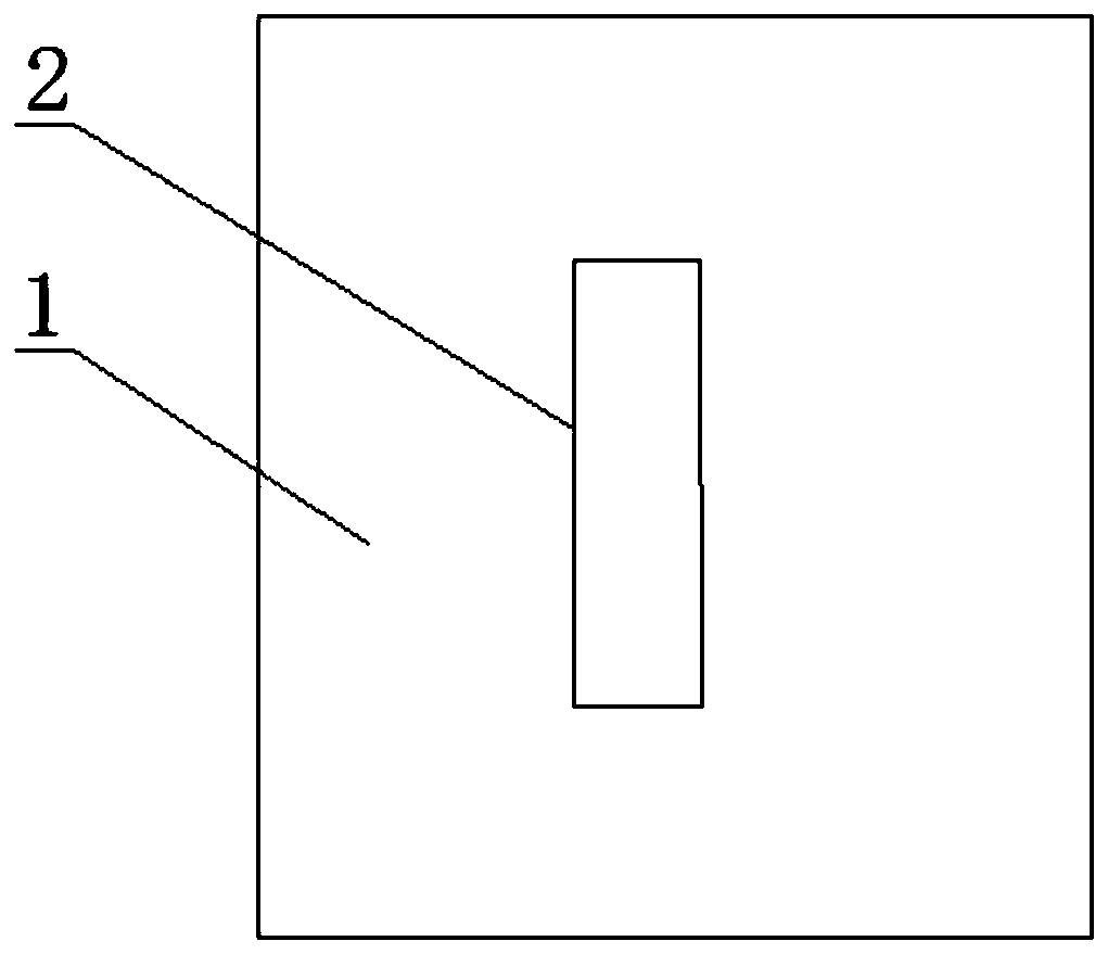
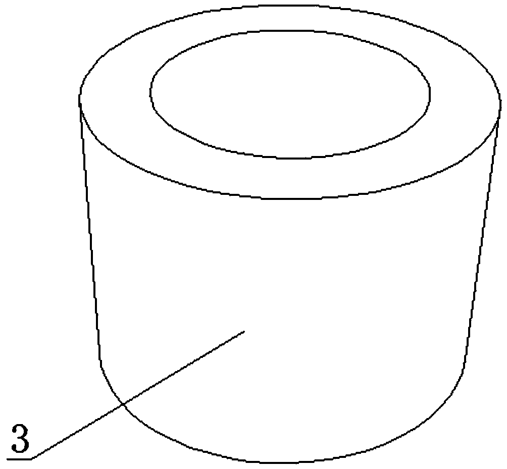
[0054] Such as Figures 1 to 9 and Figure 13-16 As shown in any of the drawings, the fully hidden door stopper includes a top cap 1, a self-locking self-resetting device 5, a bottom cylinder 3 and a fixing device, and the top cap 1 and the bottom cylinder 3 are both set to have one end closed and one end open The hollow cylindrical sleeve, the fixing device is set as a pair of fixed cylinder 4 and the card groove 2 that cooperate with each other, the card groove 2 is set as a cuboid groove structure, the fixed cylinder 4 is in the Arranged vertically, the outer wall of one end of the fixed cylinder 4 is provided with external threads, the outer wall of the other end is set as a smooth wall surface, and the two card slots 2 are symmetrically arranged on the two outer walls of the top cap 1. The outer diameter of the top cap 1 is slightly larger, and the self-locking self-resetting device 5 is arranged inside the sleeve of the top cap 1. The upper end of the top cap 1 is close...
Embodiment 2
[0063] On the basis of Example 1, different from Example 1, such as Figure 13-16 As shown, the self-locking and self-resetting device 5 includes a push rod 16, a rotating disk 13, a chute 10 and a spring, the push rod 16 is fixedly connected to the inner top surface of the top cap 1, and the lower end of the push rod 16 is connected to the top of the rotating disk 13, The bottom end of the turntable 13 is connected to the upper end of the spring, and the lower end of the spring is connected to the inner bottom surface of the bottom cylinder 3. The chute 10 is sleeved on the outer wall of the push rod 16. The chute 10 and the turntable 13 cooperate with each other to form a self-locking structure.
[0064] The turntable 13 is set as a hollow cylindrical sleeve structure, and at least one U-shaped protrusion 14 is arranged on the side wall of the turntable 13 from top to bottom, and the end of the U-shaped protrusion 14 protruding from the upper end surface of the turntable 13 i...
Embodiment 3
[0071] On the basis of Example 1, different from Example 1, such as Figure 11 As shown, the fully hidden door stopper includes a top cap 1, a self-locking and self-resetting device 5, and a bottom cylinder 3. The part above the upper end surface of the slot 2 of the top cap 1 is set as a semi-cylindrical structure, and the slot 2 of the top cap 1 The part below the upper end surface is set as a cylindrical structure that cooperates with the inner wall of the bottom cylinder 3; the bottom cylinder 3 is set as a hollow cylindrical sleeve with one end closed and one end open. Installed on the side wall of the top cap 1 through threads, the fixed cylinder 4 is vertical and protrudes from the inner wall of the top cap 1, and the outer wall of the fixed end of the fixed cylinder 4 is provided with external threads, and the outside of the engaging end of the fixed cylinder 4 The wall is set as a smooth wall surface, and the card groove 2 is set as a rectangular groove structure with...
PUM
 Abstract
Description
Claims
Application Information
 - R&D Engineer
- R&D Manager
- IP Professional
- Industry Leading Data Capabilities
- Powerful AI technology
- Patent DNA Extraction
Browse by: Latest US Patents, China's latest patents, Technical Efficacy Thesaurus, Application Domain, Technology Topic, Popular Technical Reports.
© 2024 PatSnap. All rights reserved.Legal|Privacy policy|Modern Slavery Act Transparency Statement|Sitemap|About US| Contact US: help@patsnap.com