An automatic batching and beating system

An automatic batching and beating barrel technology, applied in the pulp beating method, etc., can solve the problems of insufficient, unable to fully participate in beating and beating, and insufficient fineness of the pulp, so as to achieve high fineness, improve cross-cutting efficiency, and good beating effect Effect

Inactive Publication Date: 2018-09-07
苏州阳鹏纺织整理有限公司
View PDF1 Cites 0 Cited by
  • Summary
  • Abstract
  • Description
  • Claims
  • Application Information

AI Technical Summary

Problems solved by technology

[0004] The purpose of the present invention is to address the deficiencies of the prior art, by setting a toggle mechanism to shift the slurry on the edge of the beating barrel to the middle, and by setting two cross-cutting mechanisms below the beating mechanism to overcome the edge slurry in the beating process. The problem that the material cannot fully participate in the beating and the beating is not sufficient, and the slurry is not fine enough

Method used


Image

  • An automatic batching and beating system
  • An automatic batching and beating system
  • An automatic batching and beating system

Examples


Embodiment 1

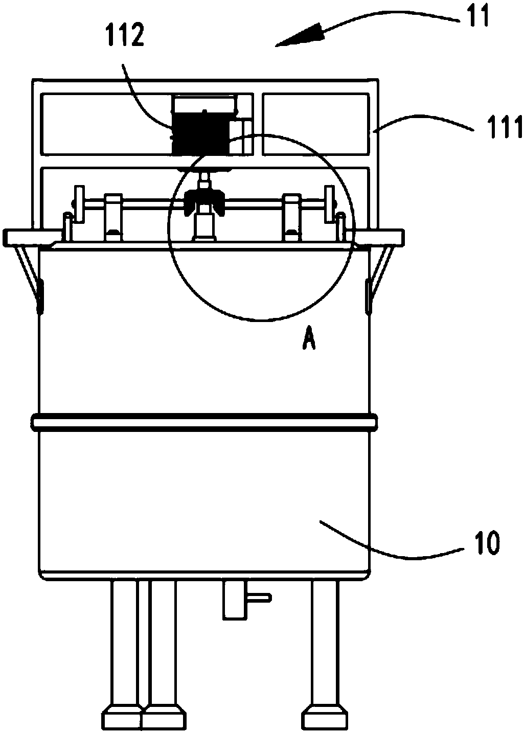
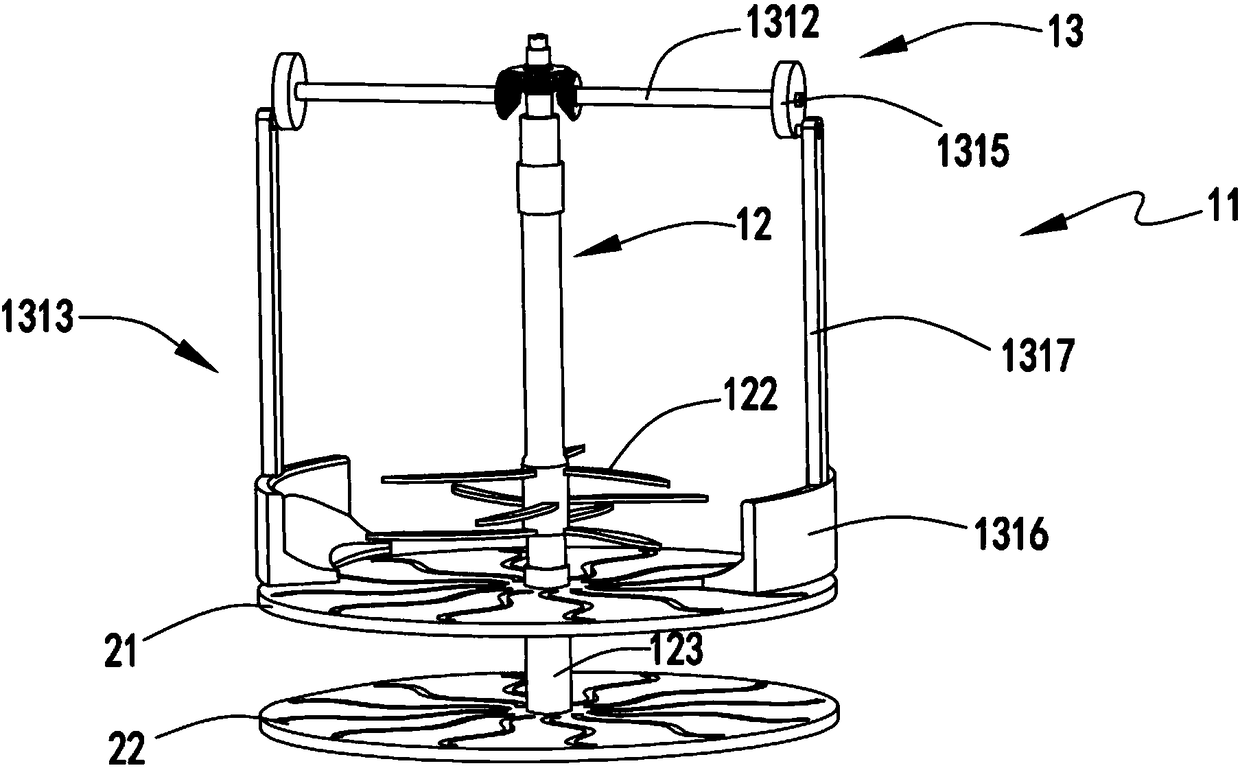
[0038] figure 1 It is a schematic diagram of the structure of the automatic batching and beating system, figure 2 It is a schematic diagram of the front view of the automatic batching and beating system, image 3 It is a partial structural diagram of the automatic batching and beating system, Figure 4 It is a schematic diagram of the cut structure of the beating barrel, Figure 5 is a schematic diagram of the chopping device, Figure 6 It is a schematic top view of the automatic batching and beating system, Figure 7 is a partial structural schematic diagram of the toggle device, Figure 8 It is a schematic diagram of the relative positional relationship between the chopping device and the blanking device, Figure 9 It is a partially enlarged schematic diagram of the primary chopping device and the primary blanking device, Figure 10 It is a partially enlarged schematic diagram of the secondary shredding device and the secondary blanking device. Such as figure 1 , ...

Embodiment 2

[0053] Such as figure 1 , figure 2 , image 3 , Figure 4 , Figure 5 , Figure 6 , Figure 7 , Figure 8 , Figure 9 and Figure 10 As shown, the components that are the same as or corresponding to those in the first embodiment are marked with the corresponding reference numerals in the first embodiment. For the sake of simplicity, only the differences from the first embodiment will be described below. The difference between the second embodiment and the first embodiment is that: the lower side of the curved groove a2112 and the curved groove b2122 are provided with a cutting knife a4 with the edge facing the counterclockwise direction, and the curved groove c2212 and The upper side of the curved groove d2222 is provided with a cutting knife b5 with the edge facing clockwise, the width of the curved groove a2112 and the curved groove b2122 is set to d1, the curved groove c2212 and the curved groove The width of d2222 is set to d2, d1 and d2 are satisfied, and d2


PUM


Abstract

The invention relates to an automatic batching beating system. The system comprises a primary beating portion and a secondary beating portion, wherein the primary beating portion comprises a power mechanism, a beating mechanism which is driven by the power mechanism to conduct beating on sizing agents in a beater tub, and a toggle mechanism which is driven by the power mechanism to stir the sizing agents on the edge of the beater tub to the center; the secondary beating portion is arranged below the primary beating portion and comprises a first-level cross-cutting mechanism and a second-level cross-cutting mechanism, the first-level cross-cutting mechanism and the second-level cross-cutting mechanism divide the beater tub into a primary sizing agent area, a secondary sizing agent area and a qualified sizing agent area from up to down in sequence, the first-level cross-cutting mechanism is used for conducing first-level cutting up on the sizing agents which flow from the primary sizing agent area to the secondary sizing agent area, and the second-level cross-cutting mechanism is used for conducting second-level cutting up on the sizing agents which flow from the secondary sizing agent area to the qualified sizing agent area; the automatic batching beating system overcomes the problems that in the process of beating, the sizing agents on the edge cannot take part in beating sufficiently, the beating is insufficient, and the sizing agents are not fine enough.

Description

technical field [0001] The invention relates to the technical field of textile beating equipment, in particular to an automatic batching and beating system. Background technique [0002] The textile industry is a traditional industry in my country, and it is also a pillar industry related to the national economy and people's livelihood. In traditional pulp and papermaking, after washing, bleaching and purification, the unbeaten pulp contains many fiber bundles. Because the fibers are too thick and too Long, the surface is smooth, stiff and elastic, the specific surface area of ​​the fiber is small and lack of bonding, if the unbeaten pulp is directly used for papermaking, it is difficult to obtain uniform distribution on the net, the paper is loose and porous, and the surface is rough and easy to fluff. The bonding strength is very low and the performance of the paper is poor, so it cannot meet the requirements of use. [0003] Authorized notification number CN204434948 U is ...

Claims


Application Information

Patent Timeline
Patent Type & Authority Patents(China)
IPC IPC(8): D21D1/02
CPCD21D1/02
Inventor 施徐哲
Owner 苏州阳鹏纺织整理有限公司
Why Eureka
Try Eureka