
Retractable rotor for aircraft vertical take-off and landing

A vertical take-off and landing, retractable technology, applied in the field of aircraft, can solve the problems of poor coordination of flight mechanism, low reliability, and inferior hinge reliability, so as to improve flight safety and robustness, improve flight stability and Effects of security, increased speed and sensitivity

Inactive Publication Date: 2017-09-08
KUNMING QIAOYI SCI & TECH CO LTD
View PDF5 Cites 1 Cited by
  • Summary
  • Abstract
  • Description
  • Claims
  • Application Information

AI Technical Summary

Problems solved by technology

(2) Low reliability
The waving of the rotor blades produces mechanical vibrations, which increases the wear of the hinges and makes the reliability always inferior to that of fixed-wing aircraft
(3) Poor roll stability
Uneven lift on both sides of the rotor can cause the rotary wing aircraft to roll, capsizing and losing control within seconds
(4) Complex manipulation
The rotor of the helicopter not only provides the maneuverability of flight, but also causes the complexity of flight control
The control load is much greater than that of fixed-wing aircraft, which increases the probability of human error
(5) Can't be bigger
The diameter and speed of the rotor are limited by the speed of the tip of the wing that cannot exceed the speed of sound. The diameter of the rotor is generally a maximum of more than ten meters. The size of the aircraft is limited and it cannot be made larger
(6) Flight mechanism disorder
Although the helicopter has been developed for nearly 70 years, the inherent coordination of the flight mechanism is poor and full of innate contradictions
For example: use the tail rotor to balance the rotor torque, use the flapping hinge and the shimmy hinge to balance the turning moment of the forward flight, the rotor area is required to be large for vertical take-off and landing, and the rotor area is expected to be small for horizontal flight, the flight mechanism of the vertical take-off and landing state and the horizontal flight state Contradictions, inability to unify, etc., directly lead to complex control of flight status and poor stability
[0004] In short, the above-mentioned defects of rotary-wing aircraft come from the contradiction between the two flight modes that the rotor needs to take into account both vertical take-off and landing and horizontal flight.

Method used


Image

  • Retractable rotor for aircraft vertical take-off and landing
  • Retractable rotor for aircraft vertical take-off and landing
  • Retractable rotor for aircraft vertical take-off and landing

Examples


Embodiment 1

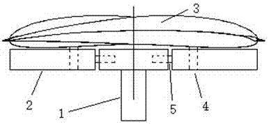
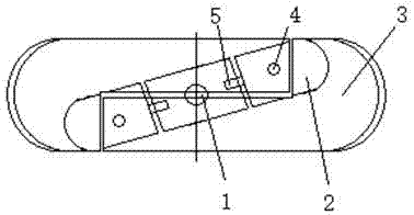
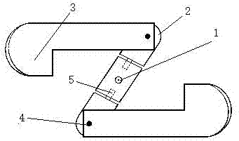
[0032] Embodiment 1: as Figure 1-5 Shown: the retractable rotor used for vertical take-off and landing of manned aircraft includes a main shaft 1, a straight beam structure blade support frame 2, two blades 3 and two blade hinges 4, and two blades installed on the blades The blade support frame 2 is connected to the collective distance hinge 5 of the blade 3 and the blade hinge 4; the main shaft 1 and the geometric center of the blade support frame 2 are vertically intersected, fixedly connected, and rotated synchronously, and the blade hinge 4 is basically parallel to the main shaft 1 , substantially perpendicular to the airfoil of the blade 3, two collective pitch hinges 5 are installed at the two ends of the blade support frame 2, and the blade hinge 4 is installed on the shaft of the collective pitch hinge 5, and the root of the blade 3 is connected to the blade The hinge 4 is connected, and the blade 3 can rotate freely around the blade hinge 4; when the two blades 3 are...

Embodiment 2

[0033] Example 2: see Figure 1-5 ,Such as Figure 6-7 As shown, the retractable rotor for manned aircraft vertical take-off and landing includes a main shaft 1, an equilateral triangle truss structure blade support frame 2, three ax-shaped blades 3 and three blade hinges 4; the main shaft 1 and the paddle The geometric center of the blade support frame 2 intersects vertically, is fixedly connected, and rotates synchronously. The blade hinge 4 is parallel to the main shaft 1 and perpendicular to the wing surface of the blade 3. The end of the blade support frame 2 and the connecting ends of the three blades 3 pass through The blade hinges 4 are connected, and the three blades 3 can rotate freely around the respective blade hinges 4; when the three blades 3 are fully opened, the blade hinges 4 and each blade 3 rotate synchronously around the main shaft 1; When the three paddles 3 are fully folded, the paddle support frame 2 and the three paddles 3 are overlapped and merged int...

Embodiment 3

[0034] Embodiment 3: see Figure 1-5 ,Such as Figure 8 As shown, the retractable rotor for manned aircraft vertical take-off and landing includes a main shaft 1, a regular quadrilateral truss structure blade support frame 2, four blades 3 and four blade hinges 4; the main shaft 1 and the blade support The geometric centers of the frame 2 intersect vertically, are fixedly connected, and rotate synchronously. The blade hinge 4 is basically parallel to the main shaft 1 and is basically perpendicular to the wing surface of the blade 3. The end of the blade support frame 2 and the connecting ends of the four blades 3 pass through the The blade hinge 4 is connected, and the four blades 3 can freely rotate around the blade hinge 4; when the four blades 3 are fully opened, the blade support frame 2, the blade hinge 4 and each blade 3 all surround the main shaft 1 Rotate synchronously; when the four paddles 3 are fully folded, the paddle support frame 2 and the four paddles 3 are ove...


PUM


Abstract

The invention provides a retractable rotor for aircraft vertical take-off and landing and belongs to the technical field of aircrafts. The retractable rotor comprises a main shaft, blade support frames, a plurality of blades and blade hinges; the main shaft is vertically intersected with and fixedly connected with the geometric center of the blade support frames, and the main shaft and the blade support frames synchronously rotate; the blade hinges are parallel to the main shaft and vertical to blade airfoils, the blades are connected with the blade support frames through the blade hinges, and the blades freely rotate around the blade hinges under the influence of centrifugal force and aerodynamic force and have different working conditions; when the blades are completely unfolded, the main shaft, the blade support frames and the blade hinges synchronously rotate around the main shaft. When the blades are folded, the blades overlap and piece a rectangle or other proper shapes; the blade support frames according to different ways are matched with the blades in a certain shape and number. The rotor aerodynamic shape can be automatically changed according to the demands of flying working conditions, and therefore resistance is reduced, lift force is increased, stationary shift and effective compatibility of working modes of vertical take-off and landing are horizontal flying are achieved, and the retractable rotor for aircraft vertical take-off and landing has the advantages of being coordinative in mechanism, simple in structure, low in cost, high in reliability, good in adaptability and the like.

Description

technical field [0001] The invention relates to a retractable rotor used for vertical take-off and landing of an aircraft, in particular to a retractable rotor that is opened during vertical take-off and landing and retracted during horizontal flight, and belongs to the technical field of aircraft. Background technique [0002] Manned aircraft can be divided into two categories: fixed wing and rotary wing. Fixed wing is commonly used in horizontal take-off and landing aircraft (such as jet airliners), while rotary wing is commonly used in vertical take-off and landing aircraft (such as helicopters). As far as the technical level has been reached so far, fixed-wing aircraft can fly at high speed and are easy to operate, but they need to rely on runways to take off and land. Rotary wing aircraft can take off and land vertically without relying on runways, and has strong adaptability, but the mechanism is out of balance, the control is complicated, the flight speed is slow, and...

Claims


Application Information

Patent Timeline
Patent Type & Authority Applications(China)
IPC IPC(8): B64C27/37
CPCB64C27/37
Inventor 杨卫华
Owner KUNMING QIAOYI SCI & TECH CO LTD
Learn More