
Vapor-assisted metal micro-droplet manufacturing device and method

A gas-phase assisted and manufacturing device technology, which is applied in the direction of additive processing, can solve the problems of high melting point of metal materials, high surface tension, and difficulty in uniformly reducing the diameter of micro-droplets, and achieve good mechanical properties and uniform metal lattice structure , Improve the effect of precision and density

Active Publication Date: 2017-09-05
BEIJING UNIV OF TECH
View PDF6 Cites 11 Cited by
  • Summary
  • Abstract
  • Description
  • Claims
  • Application Information

AI Technical Summary

Problems solved by technology

[0003] Although the micro-droplet injection technology of non-metallic materials has been maturely applied, metal materials have the characteristics of high melting point, high viscosity and high surface tension, and the formation process of metal micro-droplets involves changes in temperature and metal morphology, which is affected by many factors. Coupling effects, mature non-metallic material injection devices and control methods are difficult to be directly used in the injection manufacturing of metal materials
For metal micro-droplet jet manufacturing technology, uniform, stable and small-sized metal micro-droplets are the key to improving the quality of formed parts. A large number of scholars at home and abroad have proposed a variety of methods to control the size of micro-droplets. However, due to the nozzle hole processing technology and the limitation of the micro-droplet generation method, the diameter of the micro-droplet is difficult to reduce uniformly

Method used


Image

  • Vapor-assisted metal micro-droplet manufacturing device and method
  • Vapor-assisted metal micro-droplet manufacturing device and method
  • Vapor-assisted metal micro-droplet manufacturing device and method

Examples


Embodiment Construction

[0012] The working process and effect of a gas-phase assisted metal micro-droplet manufacturing method of the present invention will be described in detail below in conjunction with the structural drawings.

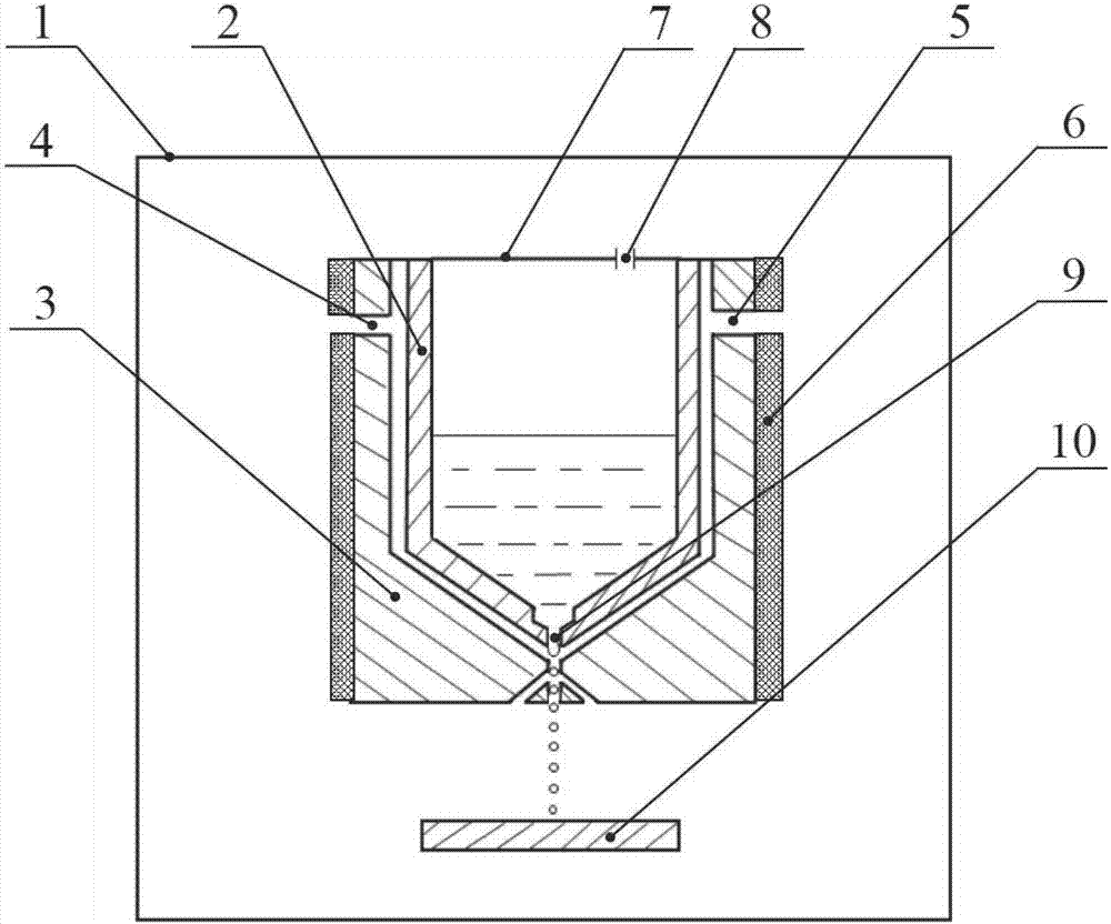
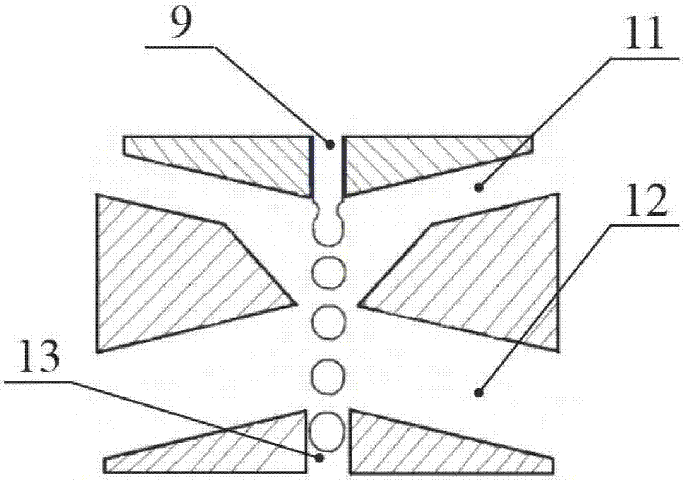
[0013] like figure 1 , figure 2 As shown, the whole device includes a sealed box 1, an inner crucible 2, an outer crucible 3, a first constant pressure gas inlet 4, a second constant pressure gas inlet 5, a heater 6, a sealing plate 7, a pulsating pressure gas inlet 8, and a liquid Outlet 9, droplet deposition platform 10, air inlet channel 11, air leakage channel 12, droplet outlet 13.

[0014] The specific working process of the device is as follows: keep the inside of the sealed box 1 in a closed environment to keep the internal temperature constant, and at the same time be an oxygen-free environment, all filled with inert gas to prevent metal oxidation; the inner crucible 2 stores liquid metal, The top of the inner crucible 2 is sealed by a sealing plate 7, and the...


PUM


Abstract

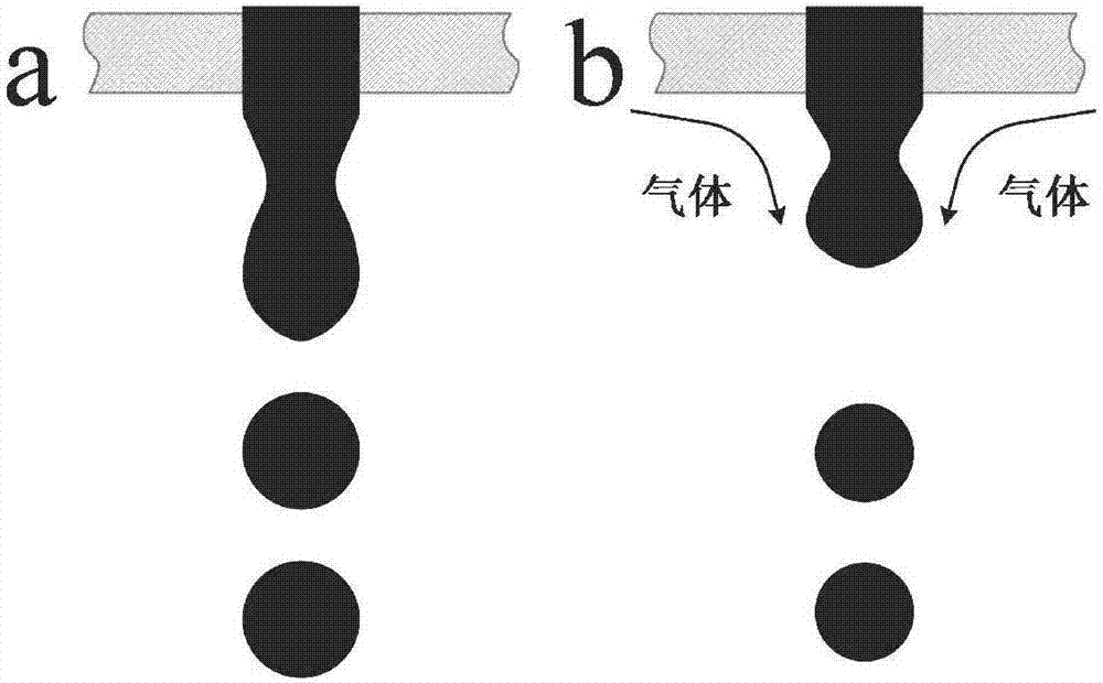
The invention discloses a vapor-assisted metal micro-droplet manufacturing device and method and belongs to a micro-droplet jetting additive manufacturing technology. The inside of a seal box body is kept in a closed environment to keep an internal temperature invariable; a liquid metal is stored in an inner crucible, an inert gas with pulsating pressure is introduced from a pulsating pressure gas inlet, and the liquid metal is extruded to flow outside from a liquid outlet; a certain distance is kept between an outer crucible and the inner crucible; a heater wraps the outside of the outer crucible to keep the temperature of an internal environment constant; a high-pressure gas flows from an air inlet passage and a flowing metal liquid is extruded and sheared at a liquid outlet; the high-pressure gas flows outside from an air leakage passage and generated micro-droplets flow outside from a droplet outlet and fall to a deposition platform. Through the viscous shearing action of the gas around the liquid outlet, advanced shear fracture of the liquid is achieved at a droplet formation stage, smaller uniform micro-droplets are generated, improvement of the accuracy and the compactness of a formed part is facilitated, a metal lattice structure is more uniform and the mechanical property is better.

Description

technical field [0001] The invention relates to a manufacturing device and method of metal micro-droplets assisted by inert gas, which are used in the micro-droplet injection additive manufacturing technology to realize the deposition of metal micro-droplets and form 3D solid shaped parts. Background technique [0002] Metal droplet jet manufacturing technology is a 3D printing technology developed based on the principle of inkjet printing. It is based on the forming principle of "discrete-superposition". Firstly, the liquid metal is controlled to generate uniform micro-droplets, and then the micro-droplets are deposited on a specific position of the substrate through the movement of the substrate, so as to realize point-by-point and layer-by-layer accumulation to form complex three-dimensional entities. structure. This technology has the advantages of simple process flow, low production cost, high density of formed parts, and good mechanical properties. It has broad applic...

Claims


Application Information

Patent Timeline
Patent Type & Authority Applications(China)
IPC IPC(8): B22F3/115B33Y10/00B33Y30/00
CPCB22F3/003B22F3/115B33Y10/00B33Y30/00
Inventor 刘赵淼王翔逄燕
Owner BEIJING UNIV OF TECH
Learn More