Resin structure, electronic component and electronic device using the same

A technology of electronic components and structures, applied in semiconductor/solid-state device parts, electrical components, devices for coating liquid on the surface, etc., can solve the problems of reduced heat dissipation, increased thermal resistance, and insufficient heat dissipation, and achieve High heat dissipation effect

Active Publication Date: 2020-04-10
PANASONIC INTELLECTUAL PROPERTY MANAGEMENT CO LTD
View PDF3 Cites 0 Cited by
  • Summary
  • Abstract
  • Description
  • Claims
  • Application Information

AI Technical Summary

Problems solved by technology

As a result, even if a large amount of filler 59 is filled, the efficiency of heat radiation from the heat dissipation member 57 will not increase.
[0009] In addition, although the water-based paint 58 that is easy to handle is used as the resin, the adhesiveness of the interface between the heat dissipation member 57 and the metal substrate 51 is insufficient.
If the adhesiveness is insufficient, the thermal resistance between the heat dissipation member 57 and the metal substrate 51 increases, so that the heat dissipation decreases.
As a result, in the structure of Patent Document 1, when the surface temperature of the heat-generating device is 200° C. or higher, or when the heat-generating area of ​​the heat-generating device is large, the conditions for obtaining an excellent heat dissipation effect are restricted. Insufficient heat dissipation inferred

Method used


Image

  • Resin structure, electronic component and electronic device using the same
  • Resin structure, electronic component and electronic device using the same
  • Resin structure, electronic component and electronic device using the same

Examples


Embodiment approach 1

[0057]

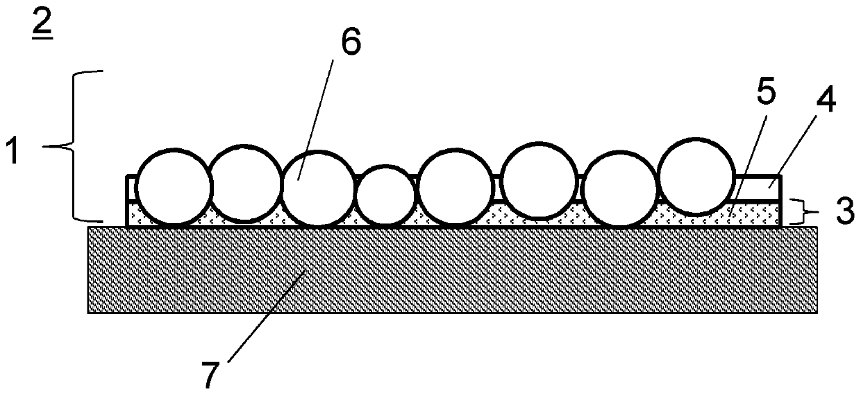
[0058] (a-1) of FIG. 1 is a cross-sectional view showing the cross-sectional structures of the resin structure 1 and the electronic component 2 according to the first embodiment. The resin structure 1 includes: a water-based paint layer 3 provided on a heating element 7 , and a resin layer 4 provided on the water-based paint layer 3 . The water-based paint layer 3 includes a water-based paint 5 and spherical fillers 6 . The spherical filler 6 is characterized in that at least a part of it exists in the water-based paint layer 3, and for more than 80% of all the fillers 6, the long axis of the filler 6 passing through the center of gravity has the water-based paint 5 with the water-based paint layer 3. The length is 1.7 times or more of the total thickness of the thickness and the thickness of the thermosetting resin of the resin layer 4 . It should be noted that the far-infrared emissivity of the filler 6 is not less than 0.8, and the average aspect ratio of the ma...

Embodiment approach 2

[0098]

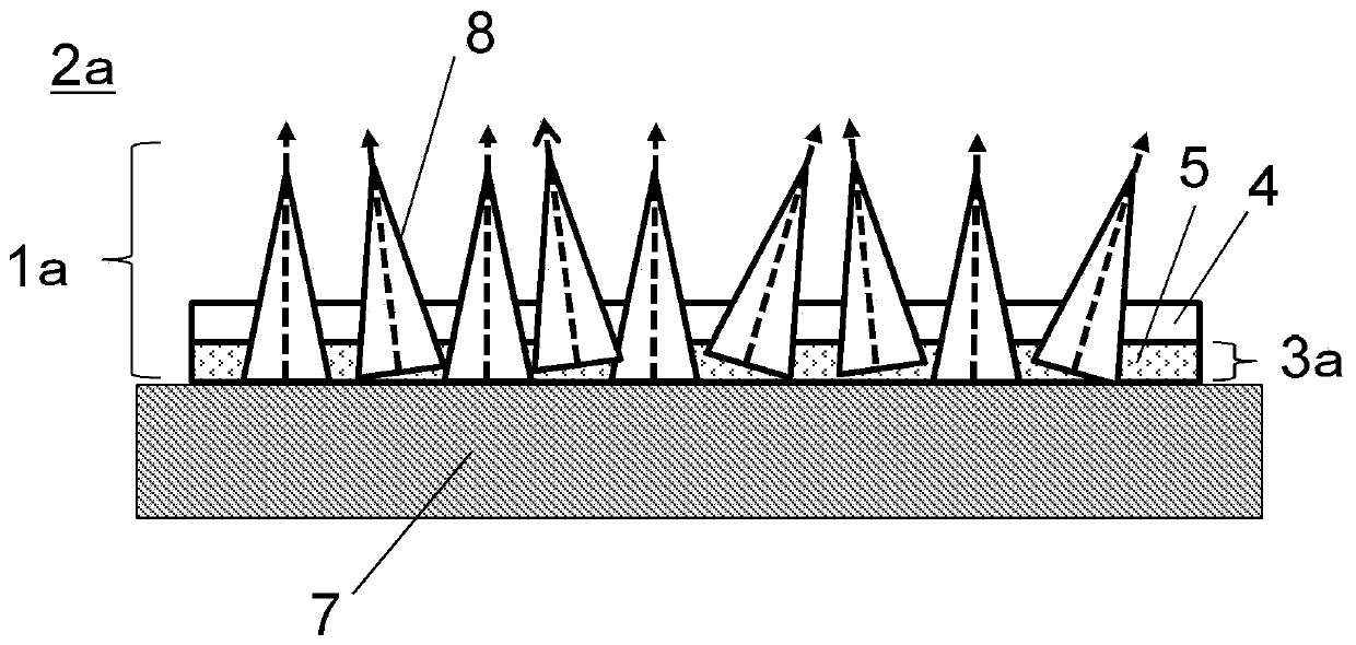
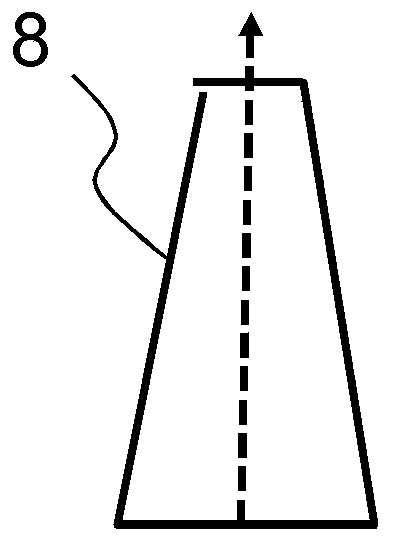
[0099] (a-2) of FIG. 1 is sectional drawing which shows the structure of the resin structure 1a of Embodiment 2, and the electronic component 2a. The resin structure 1 a of the second embodiment differs from the resin structure of the first embodiment in that the shape of the filler 8 used is not spherical but conical. This resin structure 1a includes a water-based paint layer 3a provided on a heat generating element 7, and a resin layer 4 provided on the water-based paint layer 3a. The water-based paint layer 3 a includes a water-based paint 5 and fillers 8 in the shape of pyramids or polyhedrons. The feature of this pyramidal or polyhedral filler 8 is that at least a part of it exists in the water-based paint layer 3a, and for more than 80% of all the fillers 8, the long axis passing through the center of gravity of the filler 8 has the water-based paint layer 3a. A length equal to or greater than 1.7 times the total thickness of the thickness of the coating mate...

Embodiment 1~4

[0156] According to the procedures described above in and the conditions in Table 1, the heat dissipation evaluation element 10 and the heat dissipation evaluation jig were produced.


PUM

PropertyMeasurementUnit
particle sizeaaaaaaaaaa
particle diameteraaaaaaaaaa

Abstract

The present invention provides a resin structure that has high heat dissipation properties and excellent adhesiveness at the interface with a heat-generating device. The resin structure is disposed on the base body to dissipate the heat of the base body to the outside. The resin structure includes: a water-based coating layer, which is disposed on the base body and includes the water-based coating and an average particle diameter of 30 μm or more and 150 μm or less. a filler; and a resin layer, which is provided on the water-based paint layer and contains a thermosetting resin, the far-infrared emissivity of the filler is 0.8 or more, and the average aspect ratio of the long axis and the short axis passing through the center of gravity of the filler is 1 or more and 12 or less , for more than 80% of all fillers, the long axis of the filler passing through the center of gravity has a length that is 1.7 times or more the total thickness of the water-based paint layer of the water-based paint layer and the thickness of the thermosetting resin of the resin layer.

Description

technical field [0001] The present invention relates to a resin structure that dissipates the heat of a heat generating body to the outside by thermal radiation, and electronic components and electronic devices using the structure. Background technique [0002] With the miniaturization and high density of power devices and semiconductor packages, the heat generation density of equipment has become higher. Therefore, for electronic components mounted in equipment, a technology is required to efficiently dissipate the heat generated by each component so as not to exceed the guaranteed operation temperature. [0003] Generally, fins utilizing convection and heat conduction sheets utilizing heat conduction are generally used as heat dissipation mechanisms for commercial products. However, as a commercial heat dissipation mechanism, it is difficult to dissipate heat below the operation guaranteed temperature of the heat generating device only by the conventional heat countermeas...

Claims


Application Information

Patent Timeline
Patent Type & Authority Patents(China)
IPC IPC(8): H05K7/20
CPCH05K7/2039H01L23/295H01L23/367H01L23/3737B05D7/5483H01L23/42
Inventor 名和穗菜美日野裕久
Owner PANASONIC INTELLECTUAL PROPERTY MANAGEMENT CO LTD
Why Eureka
Try Eureka