End fixture, mechanical test device and installation method

A mechanical test and fixture technology, which is applied in the field of mechanical devices and transportation, can solve the problems of unfavorable sensor paving and data line lead-out, and achieve the effect of simple structure, convenient installation and good connection

Active Publication Date: 2019-03-22
BEIJING AERONAUTIC SCI & TECH RES INST OF COMAC +1
View PDF5 Cites 0 Cited by
  • Summary
  • Abstract
  • Description
  • Claims
  • Application Information

AI Technical Summary

Problems solved by technology

[0005] If you want to further know the real-time deformation of the double-eared connecting rod under the action of static load, you need to paste the corresponding sensors on the outside of the large end of the connecting rod and the small end of the connecting rod. Test the tensile strength, compressive strength or bending strength of the connecting rod, but it is not conducive to the laying of the sensor and the lead-out of the corresponding data line

Method used


Image

  • End fixture, mechanical test device and installation method
  • End fixture, mechanical test device and installation method
  • End fixture, mechanical test device and installation method

Examples


Embodiment Construction

[0031] In order to make the object, technical solution and advantages of the present invention clearer, the present invention will be further described in detail below in combination with specific embodiments and with reference to the accompanying drawings. It should be understood that these descriptions are exemplary only, and are not intended to limit the scope of the present invention.

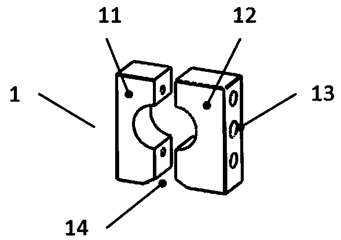
[0032] see figure 1 , figure 1 It is a structural schematic diagram of an end clamp 1 provided by the present invention.

[0033] The end clamp 1 of the present invention includes: a first U-shaped block 11 fixedly installed in the end port 51 of the double-eared connecting rod 5 through the first fastener 2 . The second U-shaped block 12 is arranged opposite to the first U-shaped block 11 and cooperates with each other, and is fixedly connected with the first U-shaped block 11 through the second fastener 6 . The end clamp 1 is located in the end port 51 of the double-eared connecting ro...


PUM


Abstract

The invention discloses an end clamp, a mechanical test device and a mounting method and belongs to the technical fields of mechanical devices and transportation. Each end clamp comprises a first U-shaped block and a second U-shaped block, wherein each first U-shaped block is fixedly mounted in an end opening of a double-ear-shaped connecting rod through a first fastener; each second U-shaped block and the corresponding first U-shaped block are arranged oppositely and matched with each other, and each second U-shaped block is fixedly connected with the corresponding first U-shaped block through a second fastener; and each end clamp is located in the corresponding end opening of the double-ear-shaped connecting rod, so that inner plug type connection is formed. According to the end clamp, the mechanical test device and the mounting method, inner plug type connection is formed between the double-U-shaped end clamps and the end openings of the double-ear-shaped connecting rod, so that good connection between the end clamps and the double-ear-shaped connecting rod is guaranteed; bonding difficulty of sensors is lowered; the sensors can be bonded to the outsides of the two ends of the double-ear-shaped connecting rod conveniently, and corresponding data lines can be guided out conveniently; and it is helpful to conduct real-time state monitoring on the double-ear-shaped connecting rod in the test process so that the real-time deformation condition of the structural component, namely the double-ear-shaped connecting rod, can be known.

Description

technical field [0001] The invention relates to the technical field of mechanical devices and transportation, in particular to an end fixture, a mechanical test device and an installation method. Background technique [0002] The two-eared connecting rod is a common structural form in the engine, which has a large connecting rod head, a small connecting rod head and a connecting rod body connected between the two. During the working process of the engine, the damage form of the connecting rod varies with the pressure conditions in the cylinder. In order to facilitate the monitoring of the damage form at both ends of the connecting rod, it is necessary to paste sensors around it in order to obtain real-time of deformation. [0003] Due to its special structural form, the damage of the double-ear connecting rod generally occurs at the openings at both ends that are prone to stress concentration. The usual static test only needs to determine its maximum tensile strength, compr...

Claims


Application Information

Patent Timeline
Patent Type & Authority Patents(China)
IPC IPC(8): B25B11/00G01M5/00
CPCB25B11/00G01M5/0058
Inventor 武玉芬张君一高丽敏
Owner BEIJING AERONAUTIC SCI & TECH RES INST OF COMAC
Why Eureka
Try Eureka