Switchgear
A technology of switch mechanism and switch part, which is applied in the direction of electric switch, switch device, switch device setting, etc., can solve the problems of SF6 gas leakage, high probability, and increased usage of SF6 gas, and achieve the goal of reducing usage and leakage Effect
- Summary
- Abstract
- Description
- Claims
- Application Information
AI Technical Summary
Problems solved by technology
Method used
Image

Examples
Embodiment 1
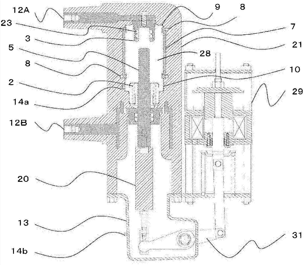
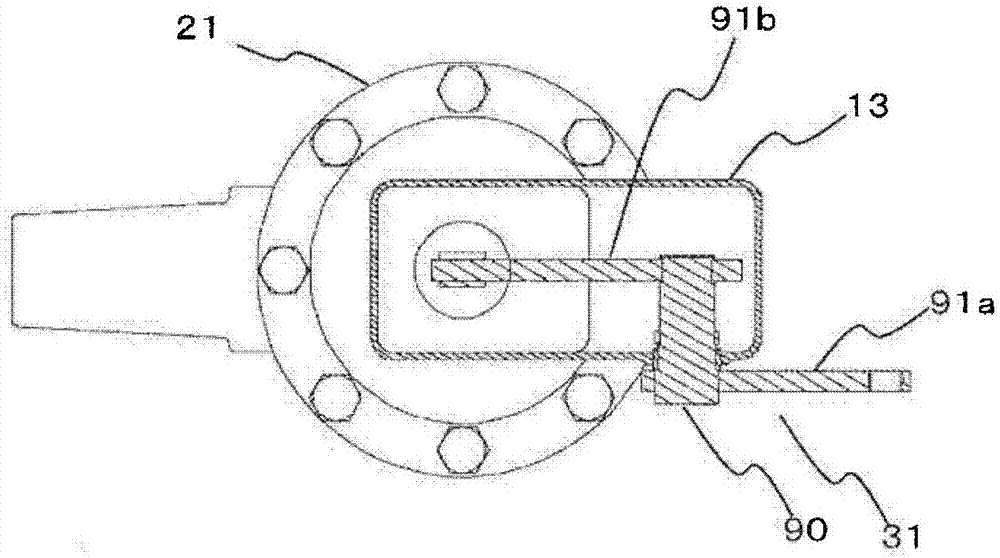
[0047] use figure 1 and figure 2 Example 1 will be described. As shown in the figure, in the gas circuit breaker of Embodiment 1, a fixed electrode 3 is arranged inside an arc extinguishing chamber composed of a ceramic insulating cylinder 7, a fixed end plate 9, a movable end plate 10, and a bellows 2, and The spring contact 23, the movable electrode 5, and the gas valve 28 formed by enclosing SF6 gas through the port 14a, the sleeve conductors 12A, 12B, and the electric field relaxation shield 8 are made of a solid insulator 21 such as epoxy resin. Perform molding. If necessary, the outer surface of the solid insulator 21 may be coated with conductive paint or the like to be at ground potential. In addition, the movable electrode 5 is driven so that it can be freely contacted and detached from the fixed electrode 3 by the two-position electromagnetic operator 29 via the insulating operating rod 20 and the control rod 31 . The insulating operating rod 20 is arranged in a...
Embodiment 2
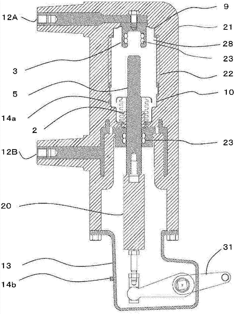
[0052] Next, use image 3 Example 2 will be described. In the gas circuit breaker of Embodiment 2, a fixed electrode 3, a movable electrode 5, and the gas valve 28 and the bushing conductors 12A, 12B, which are formed by sealing SF6 gas inside through the port 14a, are molded with a solid insulator 21 such as epoxy resin. If necessary, the outer surface of the solid insulator 21 may be coated with conductive paint or the like to be at ground potential. Other than that, it is comprised similarly to Example 1.
[0053]In this structure, the gas valve 28 is formed by mutual injection molding of the solid insulating cylinder 22, the fixed end plate 9, and the movable end plate 10 made of epoxy resin or the like, and solid insulation such as epoxy resin is used around it. Therefore, similar to Example 1, compared with the sealing structure of the O-ring, the leakage of the SF6 gas sealed inside is reduced, and the environmental suitability is high. In addition, it is only neces...
Embodiment 3
[0055] Next, use Figure 4 Example 3 will be described. In Example 3, in addition to the structure of Example 1, as shown in the figure, a solid insulating cylinder 22 and a piston 24 are arranged in the gas valve 28, and are also arranged in such a way that the central axis of the movable electrode 5 penetrates to the back of the piston 24 Through hole 25. Arc resistant metal 26 is provided on the surface of fixed electrode 3 .
[0056] In this structure, when the movable electrode 5 is driven from the ON position to the OFF position, as the volume of the space surrounded by the solid insulating cylinder 22, the piston 24, and the movable side end plate 10 decreases, the volume of the space in the space decreases. The pressure of the gas rises, and the gas is discharged from the front end of the movable electrode 5 through the through hole 25 . This gas is blown toward the arc that strikes between the movable electrode 5 and the fixed electrode 3 , thereby improving the cu...
PUM
 Abstract
Description
Claims
Application Information
 - R&D
- Intellectual Property
- Life Sciences
- Materials
- Tech Scout
- Unparalleled Data Quality
- Higher Quality Content
- 60% Fewer Hallucinations
Browse by: Latest US Patents, China's latest patents, Technical Efficacy Thesaurus, Application Domain, Technology Topic, Popular Technical Reports.
© 2025 PatSnap. All rights reserved.Legal|Privacy policy|Modern Slavery Act Transparency Statement|Sitemap|About US| Contact US: help@patsnap.com