
Sheet-shaped heat sink capable of high-efficiency heat dissipation

A heat-dissipating, radiator technology, applied in transformer/inductor cooling, transformer/inductor parts, electrical components, etc., can solve the problem that the temperature of the transformer oil cannot be reduced to an ideal level, the air flow of the heat sink is poor, and the change is hindered. Oil pressure heat dissipation and other problems, to reduce the risk of oil leakage, improve the pressure resistance, and enhance the cooling effect

Active Publication Date: 2017-08-29
CHANGSHU YOUBANG RADIATOR
View PDF7 Cites 4 Cited by
  • Summary
  • Abstract
  • Description
  • Claims
  • Application Information

AI Technical Summary

Problems solved by technology

[0003] Most of the radiators on the market today use a structure in which the oil inlet pipe, the heat sink and the oil outlet pipe are connected to dissipate heat. At present, the flow channels of most heat sinks will generate a thermal boundary layer when the transformer oil passes through, hindering the heat dissipation of the transformer oil. , and the air flow between the cooling fins is poor, resulting in the transformer oil often unable to reduce the temperature to the ideal level
[0004] In the existing technology, such as a "transformer tangential fin radiator" provided by the Chinese utility model patent authorization announcement No. ", etc., all have the above-mentioned disadvantages, and a kind of "special-shaped oil passage fin radiator" recommended by the Chinese invention patent application publication number CN106683831A, which forms irregular special-shaped oil passages by welding points to achieve The oil in the heat dissipation oil channel forms a secondary flow and destroys the thermal oil boundary layer to improve the heat transfer coefficient. However, the welding point is used to connect the front and rear heat sinks to each other, and the connection strength is low. oil spill risk

Method used


Image

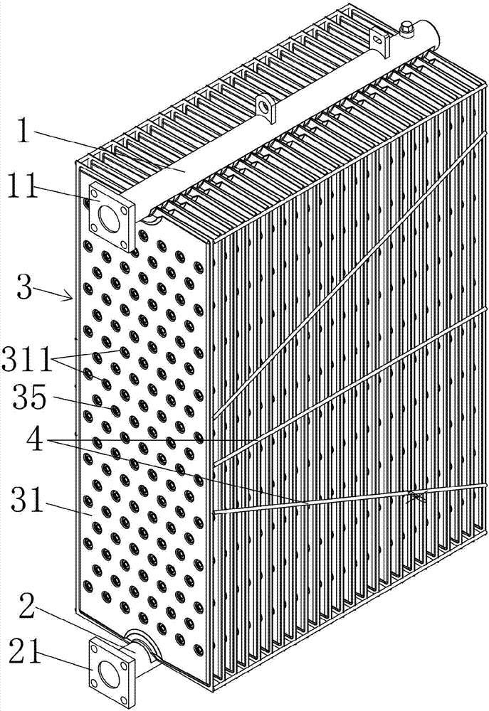
  • Sheet-shaped heat sink capable of high-efficiency heat dissipation
  • Sheet-shaped heat sink capable of high-efficiency heat dissipation
  • Sheet-shaped heat sink capable of high-efficiency heat dissipation

Examples


Embodiment Construction

[0020] The applicant will describe in detail in the form of the following examples, but the description of the examples is not a limitation to the technical solution of the present invention, and any equivalent transformation made according to the concept of the present invention is only a formal rather than a substantive equivalent transformation All should be regarded as the scope of the technical solution of the present invention.

[0021] In the following descriptions, all concepts related to directionality or orientation of up, down, left, right, front and back are based on figure 1 The position shown is a reference, so it cannot be understood as a special limitation on the technical solution provided by the present invention.

[0022] see figure 1 and combine figure 2 with image 3 , the present invention relates to a high-efficiency heat dissipation finned radiator, comprising an oil inlet pipe 1, an oil outlet pipe 2, and a group of oil inlet pipes arranged between...


PUM

PropertyMeasurementUnit
compressive strengthaaaaaaaaaa

Abstract

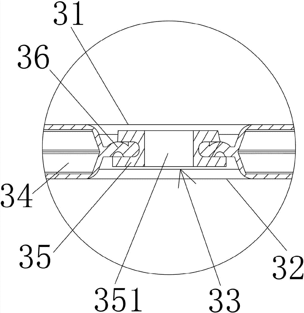
A sheet-shaped heat sink capable of high-efficiency heat dissipation comprises an oil inlet pipe, an oil outlet pipe and a group of cooling fins, wherein the cooling fins comprise a front cooling fin and a rear cooling fin, the sheet-shaped heat sink is characterized in that front flanging holes and rear flanging holes are formed in the front cooling fin and the rear cooling fin, a plurality of front flanging holes in horizontal lines are arranged at intervals from top to bottom, the front flanging holes in each horizontal line are isolated from one another, the positions of the front flanging holes on an upper horizontal line and a lower horizontal line which are adjacent to each other are staggered, the numbers of the front flanging holes and the rear flanging holes are same, the positions of the front flanging holes and the rear flanging holes are in correspondence, edges of the front flanging holes and the rear flanging holes which are in correspondence in positions are punched and integrated to a whole, a rivet hole is formed between the edges, a rivet is arranged in the rivet hole, and a heat dissipation oil duct between the front cooling fin and the rear cooling fin is partitioned to from staggered runners by the edges, which are punched and integrated, of the front flanging holes and the rear flanging holes. Secondary flow will be generated when transformer oil passes through the staggered runners, a hot oil boundary layer is broken, and the cooling effect is achieved; and the risk of oil leakage from the edges of the flanging holes is reduced, the pressure resistant strength of the cooling fins is improved, and the convective heat exchange coefficient is improved.

Description

technical field [0001] The invention belongs to the technical field of oil-immersed transformer components, and in particular relates to a high-efficiency heat dissipation fin radiator. Background technique [0002] As known in the industry, in order to ensure the long-term stable operation of the oil-immersed transformer, it is necessary to configure fin radiators on both sides of the long-side direction of the oil-immersed transformer body by means of flange connection or other similar connection methods. The radiator and the heat transfer oil inside the oil-immersed transformer form a circulating cooling circuit, which plays a role in cooling the iron core inside the oil-immersed transformer, so that the temperature rise of the oil-immersed transformer can be controlled to ensure the normal operation of the power supply and distribution system and security. [0003] Most of the radiators on the market today use a structure in which the oil inlet pipe, the heat sink and t...

Claims


Application Information

Patent Timeline
Patent Type & Authority Applications(China)
IPC IPC(8): H01F27/08H01F27/12H01F27/22
CPCH01F27/085H01F27/12H01F27/22
Inventor 王建忠陈志频瞿胜
Owner CHANGSHU YOUBANG RADIATOR
Learn More