Blade decomposition device

A blade and decomposition force technology, applied in the field of aero-engines, can solve the problems of damage to the blade surface coating, scratches, and the inability to measure the decomposition force of the compressor rotor, so as to achieve uniform decomposition force and reduce bumps and scratches.

Active Publication Date: 2019-11-12
CHINA HANGFA SOUTH IND CO LTD
View PDF15 Cites 0 Cited by
  • Summary
  • Abstract
  • Description
  • Claims
  • Application Information

AI Technical Summary

Problems solved by technology

[0004] The invention provides a blade decomposition device to solve the technical problems of damaging the blade surface coating, scratching or smashing the blade and compressor rotor, and being unable to measure the size of the decomposition force existing in the decomposition method of aluminum rods and hammers

Method used


Image

  • Blade decomposition device
  • Blade decomposition device
  • Blade decomposition device

Examples


Embodiment Construction

[0029] The embodiments of the present invention will be described in detail below with reference to the accompanying drawings, but the present invention can be implemented in many different ways defined and covered by the claims.

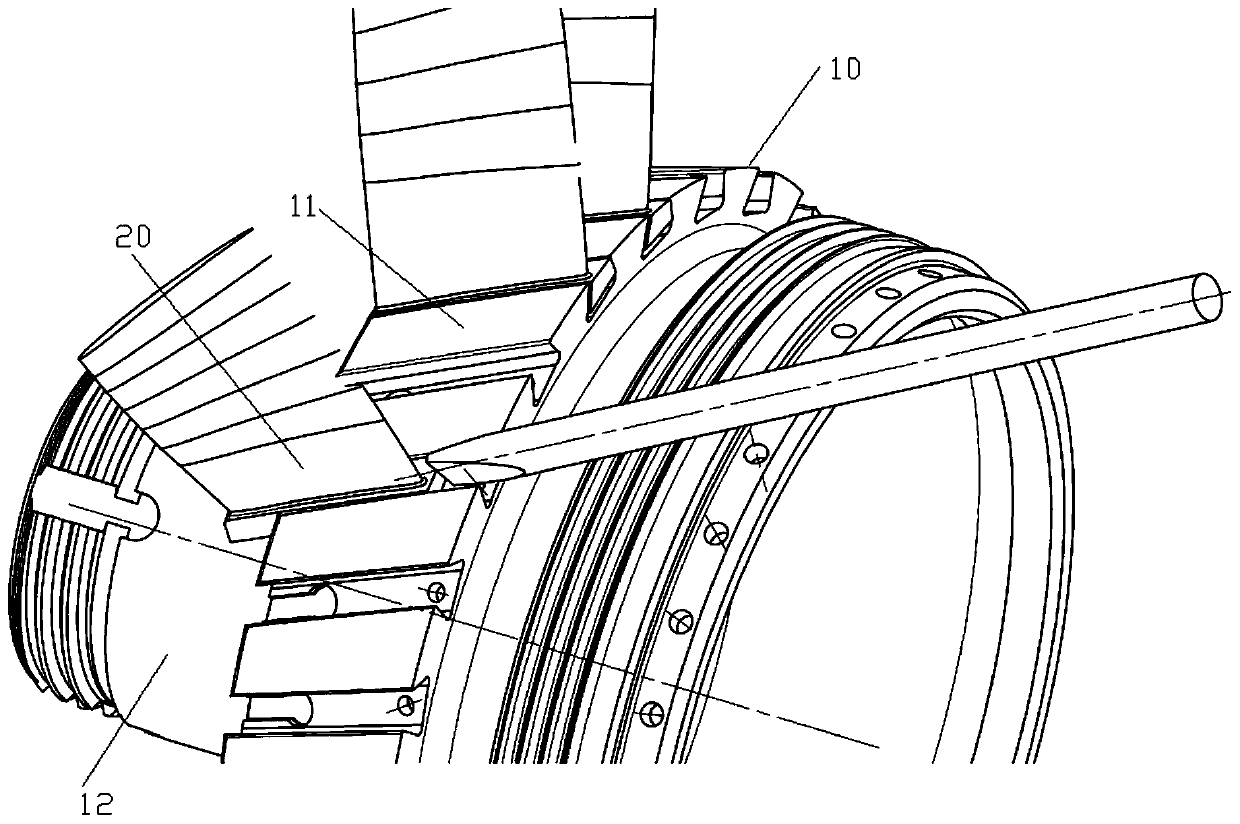
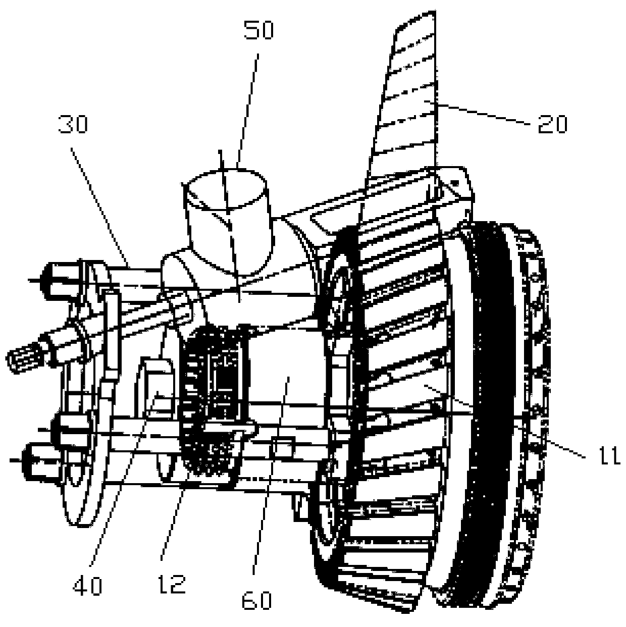
[0030] refer to figure 2 , the preferred embodiment of the present invention provides a blade decomposition device, which is used to disassemble the blade 20 installed in the mortise of the compressor rotor 10 from the mortise, and simultaneously measure the required decomposition force during the decomposition process of the blade 20 Among them, the compressor rotor 10 includes a mounting plate 11 for installing the blade 20, the mounting plate 11 is provided with a tenon groove, the end face of the mounting plate 11 is connected with the rotor shaft 12, and the outer peripheral wall of the rotor shaft 12 is provided with an outer Thread, the blade disassembly device includes: a device body 30 for being installed on the outer circle of the rotor s...


PUM


Abstract

The invention discloses a blade-disassembling device, which comprises a device body and a locking part, the device body is used for being mounted on the periphery of a rotor spindle, so that the blade-disassembling device is connected to an air compressor rotor, and the locking part is used for being mounted on the periphery of the rotor spindle to lock the device body and the air compressor rotor. A disassembling and force-measuring component which is used for disassembling a blade from a mortise and measuring the magnitude of disassembling force at the same time is connected to the device body, the disassembling and force-measuring component comprises a claw for holding the tenon of the blade, a force-measuring device which is used for measuring the magnitude of force borne by the tenon is connected to the claw, a pull rod which is used for bearing force is connected to the force-measuring device, the pull rod is slidably inserted in the device body, and a force-applying nut which is used for applying pulling force is connected to the thread of the periphery of the pull rod. The claw, the force-measuring device and the pull rod are sequentially connected along the extension direction of the mortise, so that the pull rod can pull the force-measuring device, the claw and the blade to move along the extension direction of the mortise in a direction away from a mounting disk as rotational force is applied on the nut.

Description

technical field [0001] The invention relates to the field of aero-engines, in particular to a blade disassembly device. Background technique [0002] When an engine is in working condition, the blades 20 of the compressor rotor 10 appear to move, which affects the service life of the engine, and also affects the quality of the engine, posing a threat to the safety of the aircraft and pilots. The friction force between the rotor and the rotor is measured to verify whether the friction force meets the design requirements. When verifying whether the friction force between the blade 20 and the rotor meets the design requirements, it is necessary to decompose the blade 20 from the mortise and groove of the rotor and measure the decomposition time at the same time. Bull force required. [0003] In the prior art, the disassembly of the blade 20 is knocked out with an aluminum rod and a hammer, as shown in the accompanying drawing figure 1 As shown, since the blade 20 is disassemb...

Claims


Application Information

Patent Timeline
Patent Type & Authority Patents(China)
IPC IPC(8): G01N19/04
CPCG01N19/04
Inventor 高晓龙周斌谭师师周红梅张菊绒程世扬李义勇李湘宁
Owner CHINA HANGFA SOUTH IND CO LTD
Why Eureka
Try Eureka