
Four-winding magnetic flux constraint type fault current limiter

A fault current and limiter technology, applied in electrical components, emergency protection circuit devices, etc., can solve problems such as the difficulty in accurately designing the impedance percentage of reactors, uncontrollable iron core flux, etc., and achieve low cost, short response time, and high voltage. small loss effect

Inactive Publication Date: 2017-08-18
NARI TECH CO LTD +3
View PDF5 Cites 1 Cited by
  • Summary
  • Abstract
  • Description
  • Claims
  • Application Information

AI Technical Summary

Problems solved by technology

However, the core flux of the current limiter is uncontrollable, and it is difficult to accurately design the impedance percentage of the reactor

Method used


Image

  • Four-winding magnetic flux constraint type fault current limiter
  • Four-winding magnetic flux constraint type fault current limiter
  • Four-winding magnetic flux constraint type fault current limiter

Examples


Embodiment 1

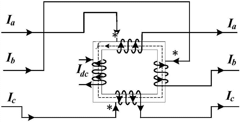
[0025] figure 1 and image 3 It is an embodiment of the present invention. Such as figure 1 As shown, the four-winding flux-constrained fault current limiter of this embodiment has a transformer core as the fault current limiter body, and the transformer core is a single-phase double-column core. Three-phase AC windings A, B and C are installed on the transformer core for connection with the three-phase line of the power grid, where the A-phase winding is connected to the A-phase line of the power grid, the B-phase winding is connected to the B-phase line of the power grid, and the C-phase winding For the C-phase line connected to the power grid, the windings of each phase are wound on the transformer core in the same direction.

[0026] Such as image 3 As shown, when a unidirectional line ground fault occurs in the power grid, such as a ground fault occurs in the C-phase line, the phase C current Ic can be controlled by the magnetic flux generated by the A-phase current ...

Embodiment 2

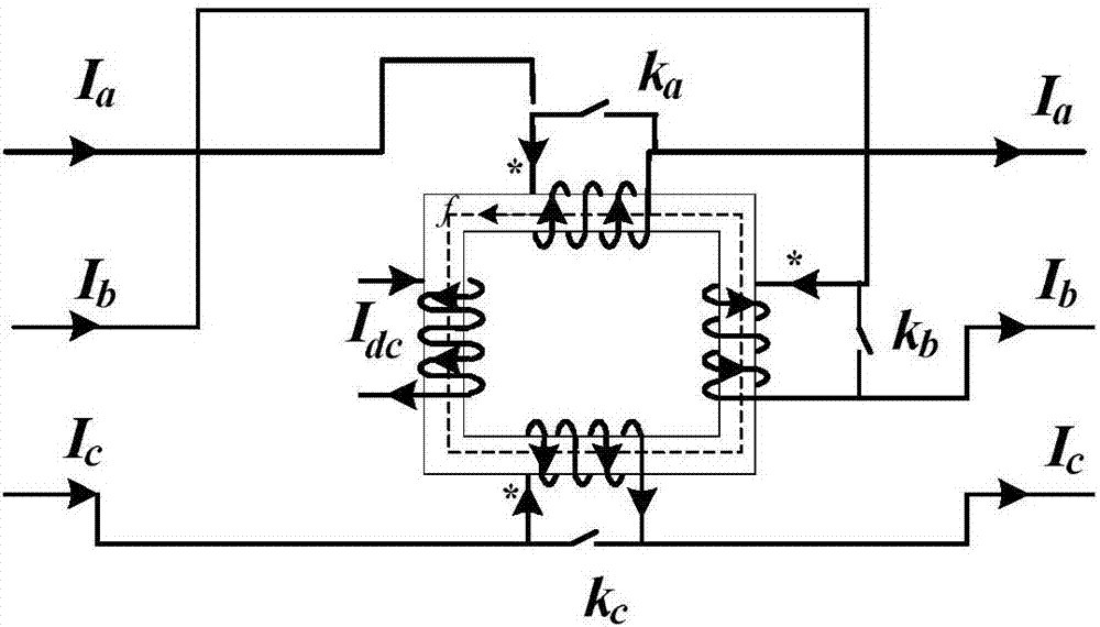
[0029] figure 2 A second embodiment of the present invention is given. The difference between this embodiment and the first embodiment is that bypass switches ka, kb and kc are also connected in parallel to the incoming and outgoing points of the windings of each phase. The bypass switch has two functions: 1) When the fault current limiter fails, the bypass switch can be used to cut off the fault current limiter; 2) After a one-way line ground fault occurs, the relay protection will cut off the faulty phase line , at this time, the bypass switch can be used to bypass the remaining non-faulted phase lines and the fault current limiter to ensure the power balance of the non-faulted phase lines, thereby maintaining the operation of the non-faulted phase lines.

[0030] Figure 4 to Figure 7 The simulated current diagram of the implementation effect of the present invention is given. Figure 4 It shows the instantaneous value of the three-phase current when the power grid is i...


PUM


Abstract

The invention discloses a four-winding flux-constrained fault current limiter, which comprises a transformer core as a fault current limiter body, three AC windings and a DC excitation winding; the three AC windings and DC excitation windings are all Wound on the transformer core in the same direction, and each AC winding is connected to one of the three-phase lines of the power grid; the DC excitation winding is powered by the DC line, and by controlling the current flow of the DC excitation winding , to control the magnetic flux in the transformer core, thereby changing the external reactance value of the fault current limiter. The invention can be applied to single-circuit transmission and distribution lines, covering 0-500KV high-voltage transmission lines. In the normal state of the system, the present invention has almost no influence on system transmission power and line current, and the voltage loss is small; when a single-phase grounding fault occurs, the fault phase current can be quickly and effectively suppressed.

Description

technical field [0001] The invention relates to a four-winding flux-constrained fault current limiter, which belongs to the technical field of short-circuit protection of power systems. Background technique [0002] As the transmission capacity of the power system continues to increase, the network architecture of the power system becomes more and more complex, and the level of short-circuit current in the power grid at all levels of the power system continues to increase. The short-circuit capacity in some areas has reached or even exceeded the interrupting capacity of the circuit breaker, while the large-capacity circuit breaker is limited by the manufacturing level and high cost, and the excessive fault current has seriously threatened the safety and stability of the power system. [0003] The fault current limiter (Fault Current Limitation, FCL) can effectively limit the transient fault current of the power grid in the fault state, and maintain the reliability and existi...

Claims


Application Information

Patent Timeline
Patent Type & Authority Applications(China)
IPC IPC(8): H02H7/26
CPCH02H7/262
Inventor 吴维宁隗华荣侯凯蒋应伟刘建平武迪叶琳张静
Owner NARI TECH CO LTD
Learn More