Flux Confined Three-Phase Fault Current Limiter
A technology of current limiter and three-phase fault, which is applied in the direction of emergency protection circuit devices, electrical components, circuit devices, etc. for limiting overcurrent/overvoltage, to achieve the effects of easy engineering, low cost and low loss of the whole machine
- Summary
- Abstract
- Description
- Claims
- Application Information
AI Technical Summary
Problems solved by technology
Method used
Image
Examples
Embodiment 1
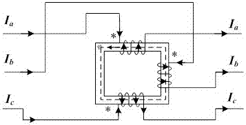
[0025] figure 1 and image 3 is an embodiment of the present invention. Such as figure 1 As shown, the flux-constrained three-phase fault current limiter of this embodiment has a transformer core as the fault current limiter body, and the transformer core is a single-phase double-column core. Three-phase coupling windings A, B and C are installed on the transformer core for connection with the three-phase line of the power grid, where the A-phase coupling winding is connected to the A-phase line of the power grid, and the B-phase coupling winding is connected to the B-phase line of the power grid. The phase coupling windings are connected to the C-phase line of the power grid, and the coupling windings of each phase are wound on the transformer core in the same direction.
[0026] Such as image 3 As shown, when a unidirectional line ground fault occurs in the power grid, such as a ground fault in the C-phase line, the magnetic flux generated by the A-phase current Ia and ...
Embodiment 2
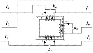
[0029] figure 2 A second embodiment of the present invention is given. The difference between this embodiment and the first embodiment is that bypass switches ka, kb and kc are respectively connected in parallel to the incoming and outgoing points of the coupled windings of each phase. The bypass switch has two functions: 1) When the fault current limiter fails, the bypass switch can be used to cut off the fault current limiter; 2) After a one-way line ground fault occurs, the relay protection will cut off the faulty phase line , at this time, the bypass switch can be used to bypass the remaining non-faulty phase lines and the fault current limiter to ensure the power balance of the non-faulty phase lines, thereby maintaining the operation of the non-faulty phase lines.
[0030] Figure 4 to Figure 7 The simulated current diagram of the implementation effect of the present invention is given. Figure 4 It shows the instantaneous value of the three-phase current when the po...
PUM
 Abstract
Description
Claims
Application Information
 - R&D
- Intellectual Property
- Life Sciences
- Materials
- Tech Scout
- Unparalleled Data Quality
- Higher Quality Content
- 60% Fewer Hallucinations
Browse by: Latest US Patents, China's latest patents, Technical Efficacy Thesaurus, Application Domain, Technology Topic, Popular Technical Reports.
© 2025 PatSnap. All rights reserved.Legal|Privacy policy|Modern Slavery Act Transparency Statement|Sitemap|About US| Contact US: help@patsnap.com


