
A Synthesis Method of Composite Left and Right Handed Leaky Wave Antenna

A technology of composite left-handed and leaky-wave antennas, applied in the direction of antenna, radiating element structure, electrical components, etc., can solve the problems of high side lobe level, high radiation efficiency, low side lobe level in the pattern, and achieve an optimized pattern performance, high radiation efficiency, the effect of optimizing the side lobe level

Inactive Publication Date: 2019-11-19
NAT SPACE SCI CENT CAS
View PDF4 Cites 0 Cited by
  • Summary
  • Abstract
  • Description
  • Claims
  • Application Information

AI Technical Summary

Problems solved by technology

[0005] The purpose of the present invention is to overcome the shortcomings of the current CRLH leaky-wave antenna that it is difficult to carry out the comprehensive design of the pattern, the loss is large, the radiation efficiency is low, and the side-lobe level of the pattern is high; a kind of CRLH leaky-wave antenna comprehensive design method is provided, the method Can design a high-performance CRLH leaky-wave antenna, which has the advantages of low loss, high radiation efficiency, and low sidelobe level

Method used

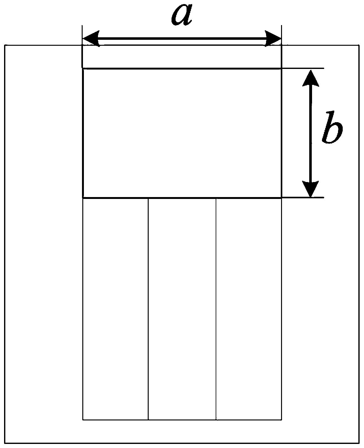
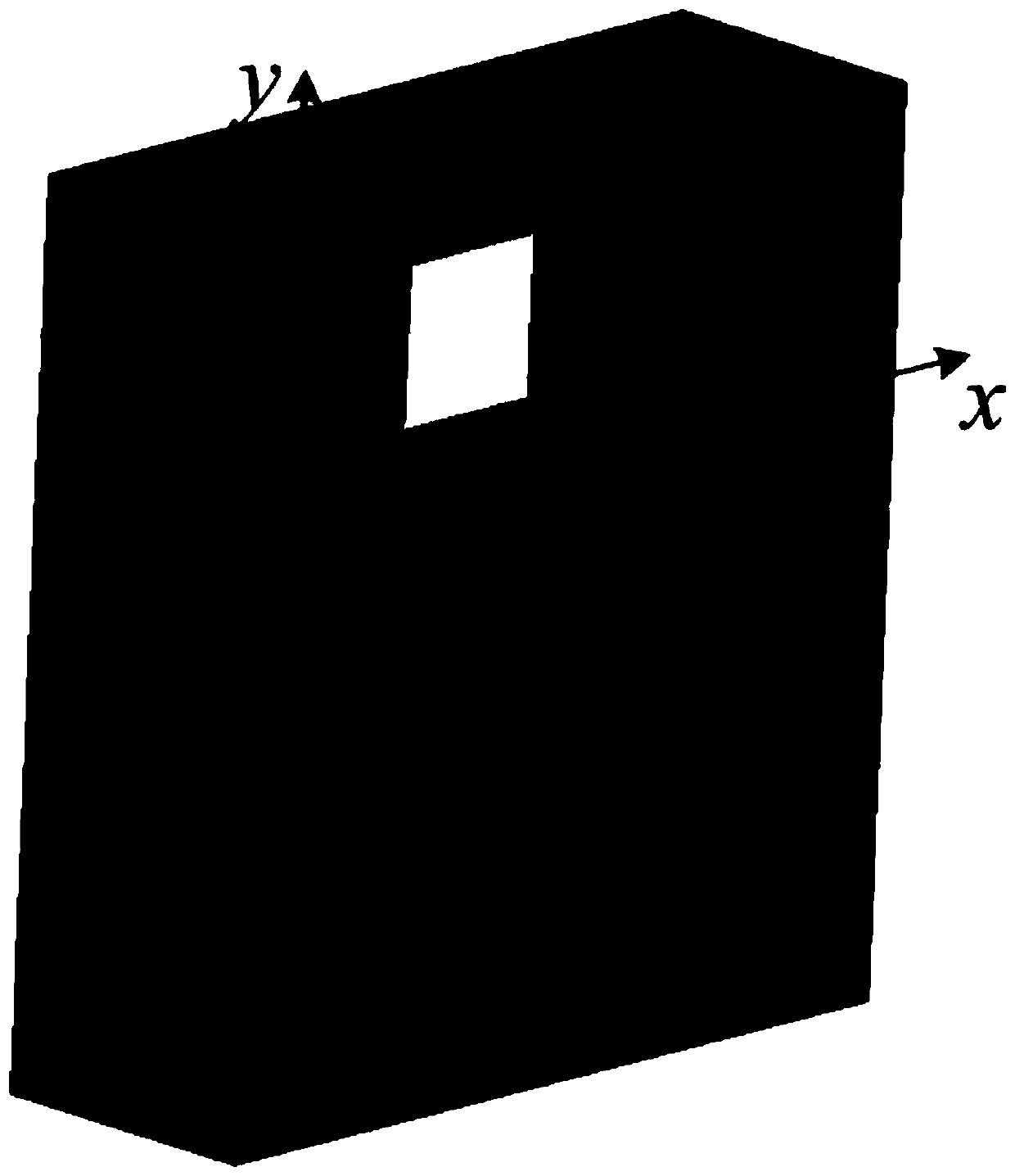
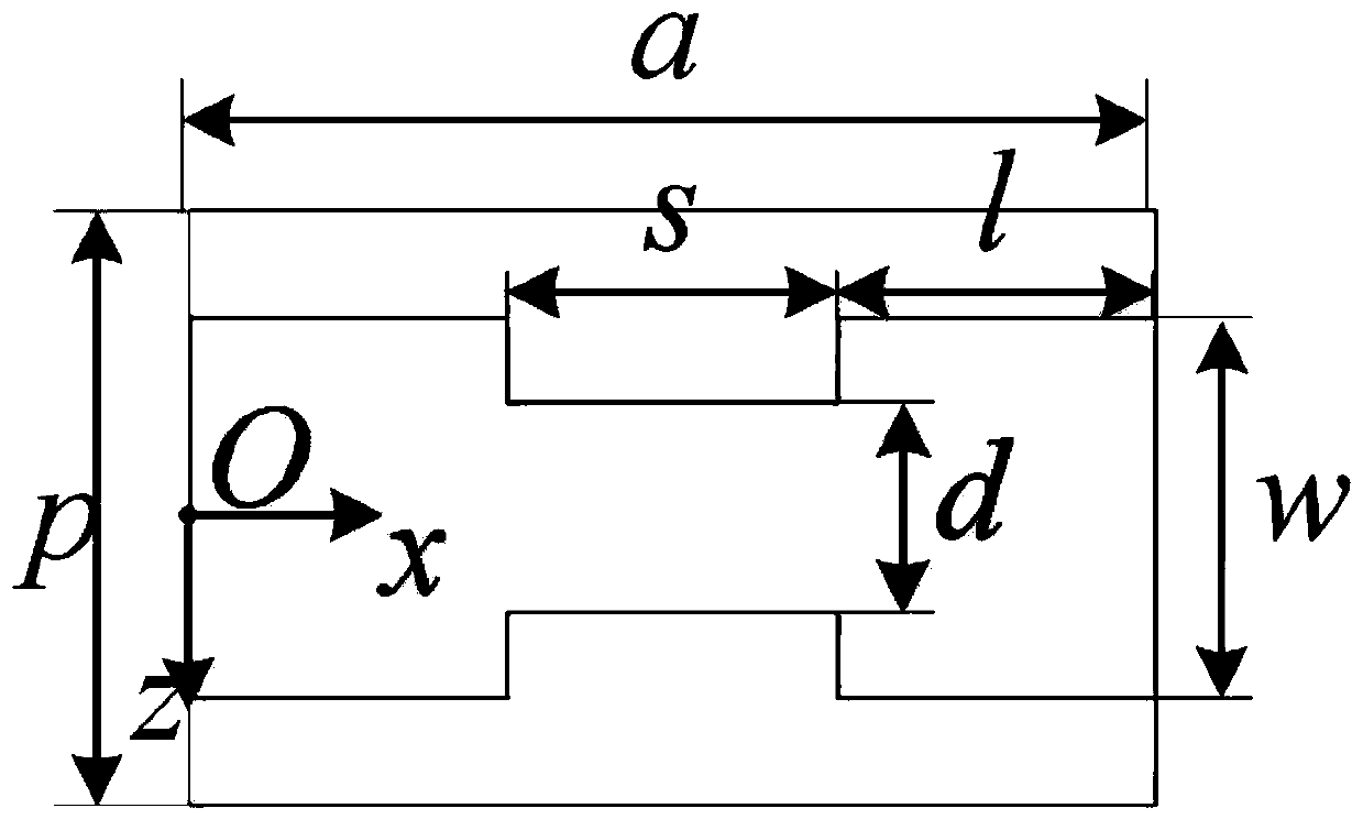

Image

  • A Synthesis Method of Composite Left and Right Handed Leaky Wave Antenna
  • A Synthesis Method of Composite Left and Right Handed Leaky Wave Antenna
  • A Synthesis Method of Composite Left and Right Handed Leaky Wave Antenna

Examples


Embodiment Construction

[0042] Before describing the embodiments of the present invention in detail, the relevant principles will be described first.

[0043] The high-performance CRLH leaky-wave antenna synthesis method of the present invention is realized based on a high-performance CRLH waveguide, and the high-performance CRLH leaky-wave antenna is composed of waveguide units with CRLH characteristics. For a traditional rectangular waveguide, the series inductance and parallel capacitance per unit length of the equivalent transmission line are

[0044]

[0045] η is the wave impedance of air, f cw is the waveguide dominant mode cutoff frequency, Z 0 is a constant and is the characteristic impedance of the rectangular waveguide. It is obvious from the above formula that when the operating frequency is below the cut-off frequency, that is, fcw , C′<0, so for the evanescent TE mode, the waveguide inherently has parallel inductance characteristics. In order to realize the left-handed characteris...


PUM


Abstract

The invention discloses a composite right and left hand leaky wave antenna. The antenna comprises N composite right and left hand waveguide units which are cascaded in a linear mode, an upper surface of each composite right and left hand waveguide unit is vertically provided with a long slit, and biasing between the long slit and a slit of a wide edge center line of the composite right and left hand waveguide unit is xd. Compared with a planar CRLH leaky wave antenna in the prior art, the CRLH leaky wave antenna has advantages of low loss, high radiation efficiency and high power capacity, integration of an antenna directional diagram can be flexibly carried out, an directional diagram sidelobe level can be optimized, and directional diagram performance is improved. The invention further provides a composite right and left hand leaky wave antenna integration method.

Description

technical field [0001] The invention relates to the field of electromagnetic microwave antennas, in particular to a synthesis method for composite left-handed and left-handed leaky-wave antennas. Background technique [0002] Composite Right / Left-Handed (CRLH) leaky-wave antennas have received extensive attention and research because of their ability to easily realize continuous beam scanning from backward to forward. So far, many CRLH leaky-wave antennas have been proposed, all of which are based on planar transmission line structures or three-dimensional waveguide structures. [0003] CRLH leaky-wave antennas with planar transmission line structure have the advantages of light weight, low profile, and easy processing, but their disadvantages of large loss and low power capacity limit their application in practical systems, and they are usually cascaded periodically CRLH radiating unit is composed of the same radiating unit, so the electromagnetic wave power leaked along t...

Claims


Application Information

Patent Timeline
Patent Type & Authority Patents(China)
IPC IPC(8): H01Q13/00H01Q1/36
CPCH01Q1/36H01Q13/00
Inventor 杨青山赵晓雯张云华
Owner NAT SPACE SCI CENT CAS
Learn More