
Compact vehicle-borne antenna lifting device

A vehicle-mounted antenna and lifting device technology, which is applied to antennas, folding antennas, electrical components, etc., can solve problems such as large driving torque or deceleration, reduced motor reliability, and lack of power-off self-locking, so as to improve reliability and improve The effect of improving the load-carrying capacity of the device and improving the waterproof and dustproof performance

Inactive Publication Date: 2017-08-18
江西中船航海仪器有限公司
View PDF8 Cites 2 Cited by
  • Summary
  • Abstract
  • Description
  • Claims
  • Application Information

AI Technical Summary

Problems solved by technology

At present, the antenna lifting devices widely used in China have antenna lifting devices with fixed angles of 0° and 90°, generally have automatic or manual single operation mode, and use cantilever force to drive the antenna, the required driving torque or deceleration is relatively large, so the general volume is relatively large Large, heavy, and poor sealing; and the compact antenna lifting device is generally driven directly by the motor, without the power-off self-locking function, and the impact force generated by the antenna when the vehicle is bumping will greatly reduce the reliability of the motor. sex

Method used


Image

  • Compact vehicle-borne antenna lifting device
  • Compact vehicle-borne antenna lifting device
  • Compact vehicle-borne antenna lifting device

Examples


Embodiment

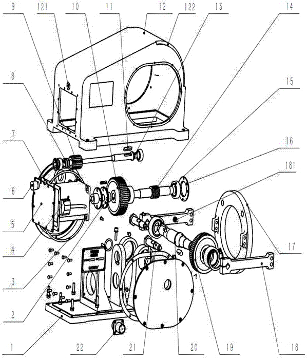
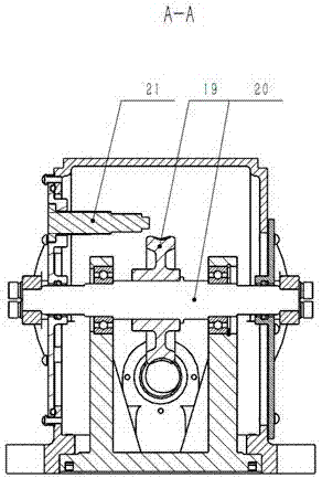
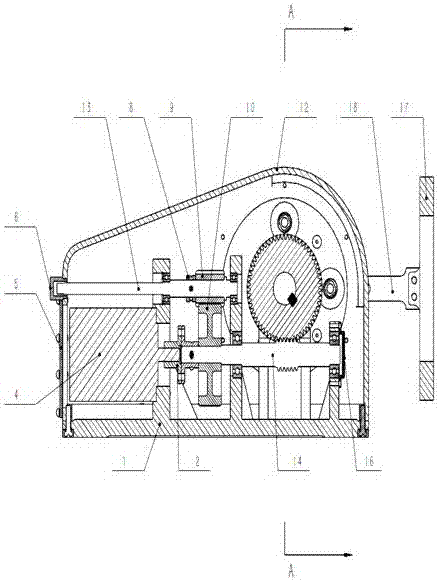
[0025] The device is connected in parallel with two sets of independent drive mechanisms, consisting of a base, a casing, a stepping motor, a worm gear mechanism, a rotating shaft, a connecting rod, an antenna mounting seat, a spur gear transmission mechanism, an operating shaft, a proximity switch, an end cover, a gasket and a seal circle composition.

[0026] The worm gear mechanism has a self-locking function, and any position of the antenna can achieve mechanical self-locking;

[0027] There is a mechanical limit structure between the connecting rod and the casing.

[0028] When the antenna mounting base is rotated to a specified position, the proximity switch outputs a closed-loop control signal, and the device is automatically protected.

[0029] The casing is provided with an end cover, a sealing gasket and a sealing ring, the operation shaft extends out of the casing and is covered with a rubber plug, and the entire device has the ability to seal and protect.

[0030...


PUM


Abstract

The invention provides a compact vehicle-borne antenna lifting device which comprises a base and a shell. The base and the shell are fastened through screws to form a cavity. The base is equipped with a stepper motor. The output end of the stepper motor is connected to a worm shaft via a coupling, the other end of the worm shaft is provided with a bearing and a bearing end cover. One side of the coupling is provided with a large gear which is connected to an operation shaft via a small gear. The worm shaft is connected to a rotation shaft via a worm wheel. Two ends of the rotation shaft extend out of the shell and are connected to connection rods. The connection rods and an antenna mounting base are connected in a fastening way, and the connection rods can rotate with the rotation shaft. The compact vehicle-borne antenna lifting device has the advantages of simple operation, high bearing capacity, high reliability, a compact structure, and good waterproof and dustproof performance.

Description

technical field [0001] The invention relates to a compact vehicle-mounted antenna lifting device. Background technique [0002] With the rapid development of information technology, the demand for communication between military, police and civilian vehicles has become stronger and stronger, and the number of vehicles equipped with antennas has increased. When the antenna is raised, it can send and receive long-distance wireless information, but When vehicles pass through culverts, bridge openings, and tunnels, in order to avoid antenna damage and facilitate vehicle passage, the antenna needs to be lowered to the level. At present, the antenna lifting devices widely used in China have antenna lifting with fixed angles of 0° and 90°. Generally, they have automatic or manual single operation mode, and use cantilever force to drive the antenna. The required driving torque or deceleration is relatively large, so the general volume is relatively large. It is large, heavy, and has...

Claims


Application Information

Patent Timeline
Patent Type & Authority Applications(China)
IPC IPC(8): H01Q1/08H01Q3/06
CPCH01Q1/08H01Q3/06
Inventor 胡育勇廖国民习细保雷同琼刘晓辉
Owner 江西中船航海仪器有限公司
Learn More