
Battery cell hole ironing mechanism and winder thereof

A battery core and hole-scalding needle technology is applied in the field of a battery-core hole-scalding mechanism and its winding machine, which can solve the problems of deformation and rebound of the center reaming hole, low production efficiency, etc. The effect of diaphragm rebound

Active Publication Date: 2017-08-18
ZHUHAI HIGRAND ELECTRONICS TECH
View PDF4 Cites 6 Cited by
  • Summary
  • Abstract
  • Description
  • Claims
  • Application Information

AI Technical Summary

Problems solved by technology

[0007] In order to solve the problems of low production efficiency and deformation and rebound of the center reaming hole in the prior art, the invention provides a simple structure, which realizes automatic hole ironing processing, improves the quality and production efficiency of the battery core, and the battery core after ironing the hole can make the battery The electric core ironing mechanism and its winding machine with the core placed for a longer time and the center hole not rebounding

Method used


Image

  • Battery cell hole ironing mechanism and winder thereof
  • Battery cell hole ironing mechanism and winder thereof
  • Battery cell hole ironing mechanism and winder thereof

Examples


Embodiment Construction

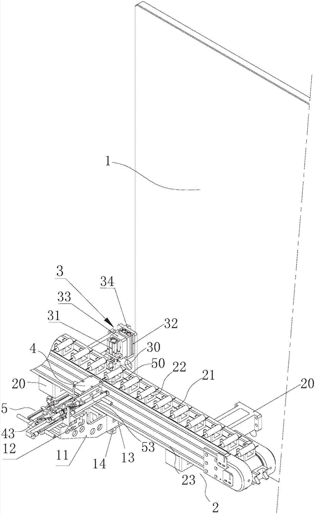
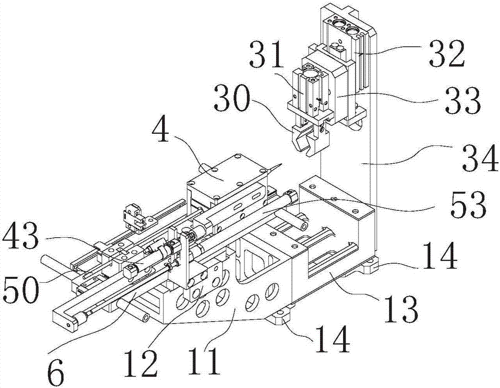
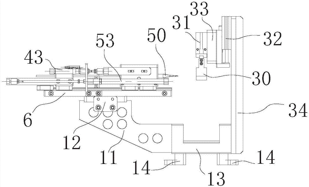
[0036] The core ironing mechanism is mainly used in cylindrical lithium-ion battery automatic winding machines or cylindrical lithium-ion film making and winding integrated machines, such as Figure 1 to Figure 8 As shown, it includes a vertically arranged substrate 1, and a cell conveying part 2 is provided on the front side of the substrate to convey the cylindrical cells wound by the winding machine one by one, and the substrate 1 is also provided with a cell conveying unit. The cell clamping and positioning part 3 for clamping and positioning each cell conveyed on part 2, the ironing needle heating part 4, and the center ironing round hole processing for each cell clamped and fixed by the cell clamping and positioning part 3 The ironing needle feeding part 5 of the ironing needle; after passing through the electric core ironing mechanism, the electric core that originally passed through the reamed hole is ironed by the heated ironing needle, so that the center hole of the e...


PUM


Abstract

The invention provides a battery cell hole ironing mechanism which comprises a baseplate. A battery cell conveying portion for conveying batter cells one by one in order is arranged on the front side of the baseplate, and a battery cell clamping and positioning portion for clamping and positioning each battery cell conveyed on the battery core conveying portion, an ironing needle heating portion and an ironing needle feeding portion for iron a round hole in the center of each battery cell clamped and fixed by the battery cell clamping and positioning portion are arranged on each of two sides of the battery cell conveying portion; each ironing needle feeding portion comprises a hole ironing needle, a sliding rail, a slider seat arranged on the sliding rail and convenient for mounting and fixing the ironing needle hole and an ironing needle feeding cylinder, and each ironing needle feeding cylinder pushes the corresponding slider seat and the corresponding hole ironing needle to move forwards along the corresponding sliding rail to be inserted into the center of the corresponding battery cell clamped by the corresponding battery cell clamping and positioning portion or move backwards to exit the center of the corresponding battery cell for resetting; each heating displacement cylinder pushes a heating block to move forwards along the corresponding sliding rail to the edge of the center of the corresponding battery cell for hole ironing to heat the front portion of the hole ironing needle inserted into the corresponding battery cell to accelerate hole ironing at the center of the battery cell. The invention further provides a winder adopting the battery cell hole ironing mechanism.

Description

[0001] 【Technical field】 [0002] The invention relates to lithium battery processing technology, in particular to a battery core ironing mechanism and a winding machine thereof. [0003] 【Background technique】 [0004] At present, in the production of cylindrical batteries, domestic manufacturers need to pass the welding pins through the center hole, or insert conductive pins in the center hole of the battery according to the needs, so it is necessary Reaming and ironing are performed on the wound battery core to ensure that the diaphragm in the center hole will not be damaged when the bottom is welded and the conductive pin is inserted, resulting in a short circuit of the internal resistance. [0005] In the production process of this process, the existing manufacturers ream the hole at the center hole, and most of them adopt the circular extrusion and expansion method of the needle roll. The diaphragm of the center hole after expansion by this method is easy to rebound. In t...

Claims


Application Information

Patent Timeline
IPC IPC(8): H01M10/04H01M10/0587H01M10/058
CPCH01M10/0404H01M10/058H01M10/0587Y02E60/10Y02P70/50
Inventor 曹海霞杨春超刘秀娟赵冠男
Owner ZHUHAI HIGRAND ELECTRONICS TECH
Learn More