
A mobile robot positioning method based on laser scanner and strong reflective signs

A technology of laser scanners and mobile robots, which is applied in manipulators, program-controlled manipulators, manufacturing tools, etc., can solve problems such as the impact of sensory camera performance, and achieve the effects of reducing system complexity, algorithm complexity, and less changes

Active Publication Date: 2019-07-09
山科华智(山东)机器人智能科技有限责任公司
View PDF2 Cites 2 Cited by
  • Summary
  • Abstract
  • Description
  • Claims
  • Application Information

AI Technical Summary

Problems solved by technology

The disadvantage of this method is that the path and marker points of the robot need to be drawn in advance, and the performance of the perception camera will be affected to a certain extent when the rain, snow or light changes drastically.

Method used


Image

  • A mobile robot positioning method based on laser scanner and strong reflective signs
  • A mobile robot positioning method based on laser scanner and strong reflective signs
  • A mobile robot positioning method based on laser scanner and strong reflective signs

Examples


Embodiment Construction

[0041] The present invention is described in detail below in conjunction with accompanying drawing:

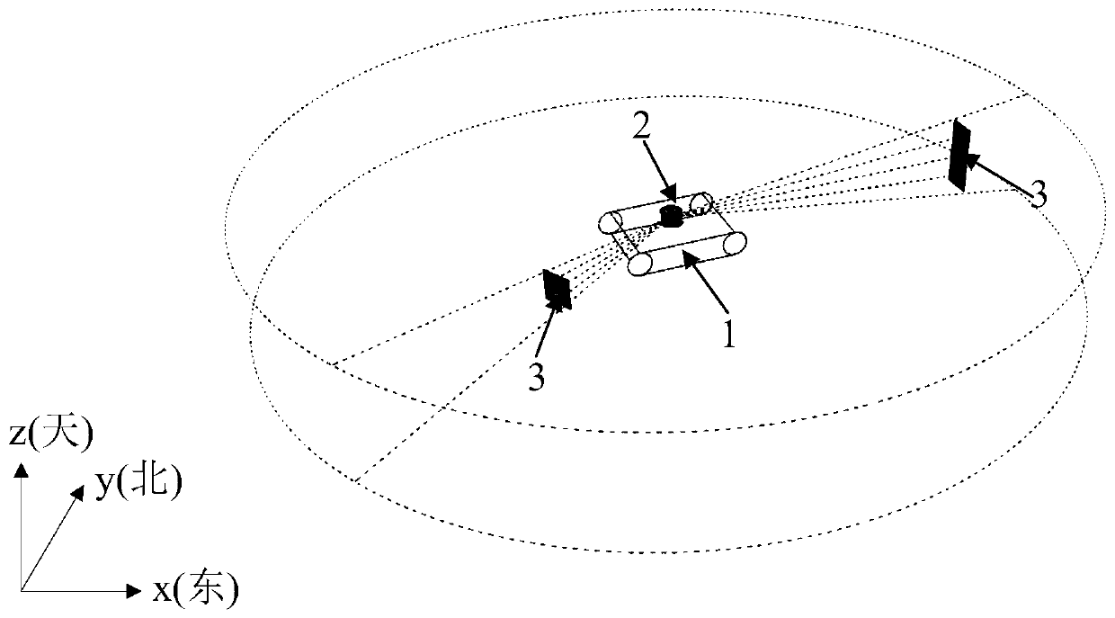
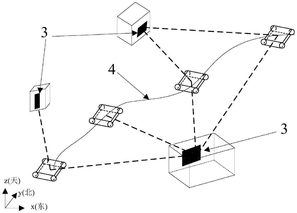
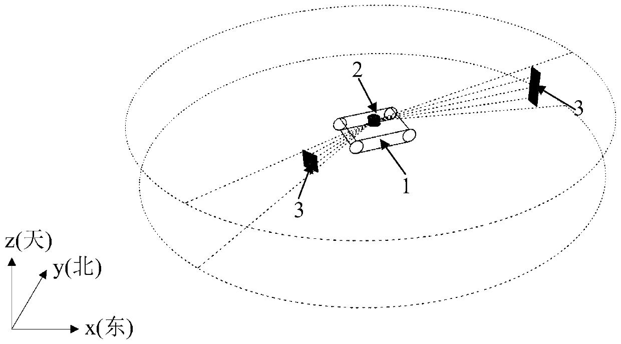
[0042]The invention discloses a positioning method for a mobile robot 1 based on a laser scanner 2 and a strong reflective mark 3. The basic principle of the method is to construct an environment monitoring mobile robot 1 composed of a multi-line laser scanner 2 and a strong reflective mark 3 The system uses the ambient light intensity data and distance data obtained by the multi-line laser scanner 2 to realize the identification and relative positioning of the strong reflective sign 3, and then calculates the distance and slope information of the two lines connecting the reflective signs, and then realizes the reflection through data matching. The global positioning of the sign, and finally the position information acquisition of the robot 1 in the global environment is realized through the relative positional relationship between the robot 1 and the reflective sign.

[0043]...


PUM


Abstract

The invention discloses a mobile robot positioning method based on a laser scanner and strong reflective signs. The method comprises that steps that a mobile robot environment monitoring system composed of the multi-line laser scanner and the strong reflective signs is established, and the strong reflective signs are recognized and relatively positioned through environment light intensity data and distance data obtained by the multi-line laser scanner. When the initial position of the robot is not known, distance and gradient information of pairs of connected lines of the reflective signs is calculated, therefore global positioning of the reflective signs is achieved through data matching, and finally position information acquisition of the robot under the global environment is achieved through the relative position relation between the robot and the reflective signs. The mobile robot positioning method has the beneficial effects that the defects that perceptual information is excessively simple when only distance or direction data are adopted, and less target characteristics are obtained are overcome, and recognition stability is improved.

Description

technical field [0001] The invention relates to the technical field of mobile robot positioning, in particular to a laser scanner-based mobile robot positioning method. Background technique [0002] With the rapid development of robot technology, mobile robots have a wide range of application requirements in the fields of warehousing logistics, intelligent inspection, mobile operation and so on. When a robot performs tasks autonomously, its location information in the environment is the key to motion planning. Taking the substation intelligent inspection robot as an example, it often uses methods such as embedding magnetic materials on the road surface or pasting RFID tags to realize the positioning and navigation of the robot. This type of method can meet the requirements of autonomous operation of the robot, but requires major changes to the on-site environment, and the maintenance work when problems occur are also very cumbersome. Therefore, with the development of robo...

Claims


Application Information

Patent Timeline
Patent Type & Authority Patents(China)
IPC IPC(8): B25J13/08B25J19/02B25J9/16
CPCB25J9/1653B25J13/089B25J19/022
Inventor 张慧王斌鹏李贻斌李彬
Owner 山科华智(山东)机器人智能科技有限责任公司
Learn More