
Welding process for automobile connecting rod assembly

A welding process and connecting rod technology, used in welding equipment, auxiliary welding equipment, welding/cutting auxiliary equipment, etc., can solve the problems of increasing the risk of hydrogen embrittlement of welds and reducing the fatigue performance of welds, and reduce hydrogen embrittlement. risk, improve welding quality, and facilitate the effect of hydrogen removal

Inactive Publication Date: 2017-08-18
四川望锦机械有限公司
View PDF5 Cites 0 Cited by
  • Summary
  • Abstract
  • Description
  • Claims
  • Application Information

AI Technical Summary

Problems solved by technology

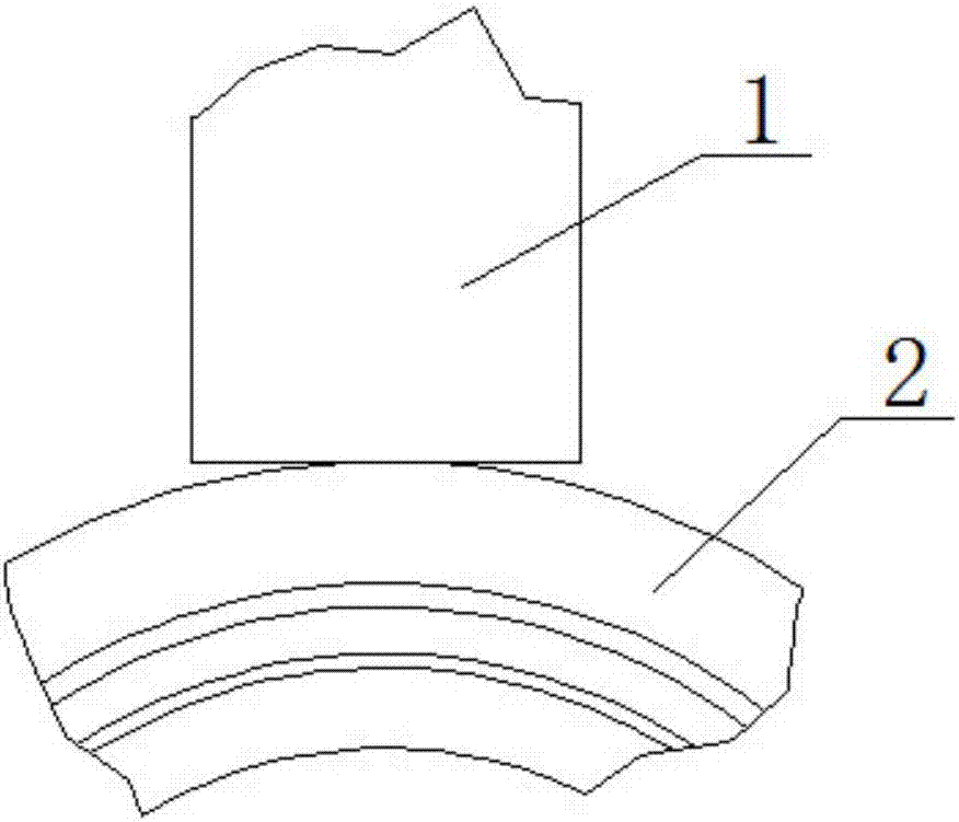
[0002] The existing automobile connecting rod assembly usually includes a connecting rod and a ball pin sleeve. The connecting rod and the ball pin sleeve are usually welded to form a fixed connection. During the welding process, since there is a welding end of the connecting rod The chamfered boss, therefore, during the spot welding process, the boss material is compressed to form a hemispherical weld instead of a circular arc transition weld, resulting in a decrease in the fatigue performance of the weld; and, due to the existing automobile connecting rod The connecting rods in the assembly are mostly made of 40Cr, which has a high carbon content, and the ball pin bushings are mostly made of 20# material, which is rapidly cooled in the air after welding, which will easily cause cracks during rapid cooling. The hardened structure (martensitic structure) that is very sensitive to cold cracks. At the same time, when the cooling rate is large in the superheated zone, it is easy to form hard and brittle high-carbon martensite, which makes the superheated zone brittle and increases Risk of hydrogen embrittlement in welds

Method used


Image

  • Welding process for automobile connecting rod assembly
  • Welding process for automobile connecting rod assembly
  • Welding process for automobile connecting rod assembly

Examples


Embodiment Construction

[0018] In order to make the object, technical solution and advantages of the present invention clearer, the present invention will be described in detail below in conjunction with the accompanying drawings and specific embodiments. It should be understood that the specific embodiments described here are only used to explain the present invention, not to limit the present invention.

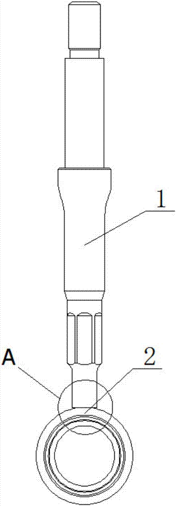
[0019] Such as figure 1 , figure 2 The automobile connecting rod assembly shown mainly includes a connecting rod 1 and a ball pin sleeve 2, and the connecting rod 1 and the ball pin sleeve 2 are usually fixedly connected by welding. Wherein, described welding method can adopt such as image 3 The welding process shown is carried out, specifically:

[0020] First, assemble according to the structure of the automobile connecting rod assembly product, that is, prepare the required connecting rod 1 and ball pin sleeve 2.

[0021] Then, before the connecting rod 1 and the ball pin sleeve 2 are wel...


PUM


Abstract

The invention provides a welding process for an automobile connecting rod assembly. The automobile connecting rod assembly comprises a connecting rod and a ball pin sleeve. The connecting rod and the ball pin sleeve are fixedly connected in a welding mode. Moreover, after the connecting rod and the ball pin sleeve are welded, insulation treatment can be conducted at the welding position for a certain period of time. According to the welding process, the welding position is subjected to insulation treatment for a certain period of time, the carbon content of welded joints formed after welding is lowered, and the problem that a quenched structure (martensitic structure) sensitive to cold cracks can be obtained easily during rapid cooling of the welding position is solved; and meanwhile, the problem that hard and brittle high-carbon martensite can be formed easily when the cooling speed of an overheated zone is high, and thus the overheated zone can be embrittled can be solved, removal of hydrogen of the welded joints can be facilitated, and therefore the hydrogen embrittlement danger of the welded joints after welding is lowered, welding quality of automobile connecting rod assembly products can be better improved, and the service life of the automobile connecting rod assembly products can be prolonged.

Description

technical field [0001] The invention relates to the technical field of welding of an automobile connecting rod assembly, in particular to a welding process of an automobile connecting rod assembly. Background technique [0002] The existing automobile connecting rod assembly usually includes a connecting rod and a ball pin sleeve. The connecting rod and the ball pin sleeve are usually welded to form a fixed connection. During the welding process, since there is a welding end of the connecting rod The chamfered boss, therefore, during the spot welding process, the boss material is compressed to form a hemispherical weld instead of a circular arc transition weld, resulting in a decrease in the fatigue performance of the weld; and, due to the existing automobile connecting rod The connecting rods in the assembly are mostly made of 40Cr, which has a high carbon content, and the ball pin bushings are mostly made of 20# material, which is rapidly cooled in the air after welding, w...

Claims


Application Information

Patent Timeline
Patent Type & Authority Applications(China)
IPC IPC(8): B23K37/00
CPCB23K37/00
Inventor 周后火
Owner 四川望锦机械有限公司
Learn More