


Quick Research
Generate reliable direction feasibility study reports for your R&D in just a few steps.

Technical Q&A
Discover and master advanced knowledge NOW. Basics, ideas, possibilities, all at once.

Find Solutions
As an expert in R&D theories, this can generate solutions to your technical problems instantly.

Evaluate Feasibility
Analyze your overall solution with one click, know your potential R&D risks in advance.

Monitor Landscape
Get weekly tech updates, stay abreast of the latest tech innovations and key insights.
A punching process for tripod workpiece
A processing technology and workpiece technology, which is applied in the field of punching processing technology for tripod workpieces, can solve the problems of easy positioning punching, regular shape of exhaust pipe, low work efficiency, etc., to avoid compression deformation and high punching accuracy , the effect of fast processing speed
- Summary
- Abstract
- Description
- Claims
- Application Information
AI Technical Summary
Problems solved by technology
Method used
Image

Examples
Embodiment 1
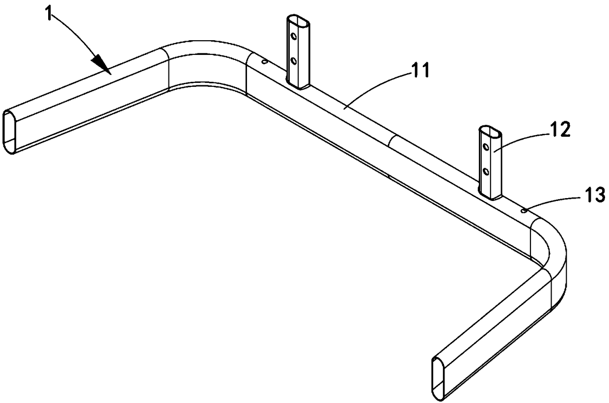
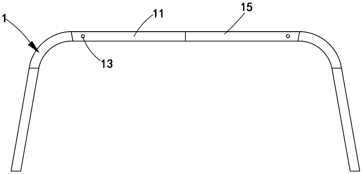
[0039] Such as figure 2 and image 3 As shown, a tripod workpiece includes:
[0040] An elbow 11, the two sides of the elbow 11 are bent symmetrically;
[0041] The connecting piece 12 is symmetrically arranged on the upper arc surface of the elbow 11 and is fixedly connected with the elbow 11 by welding.
[0042] It should be noted that the number of connectors 12 is not limited to the two mentioned in this embodiment, and can be changed according to actual production conditions.
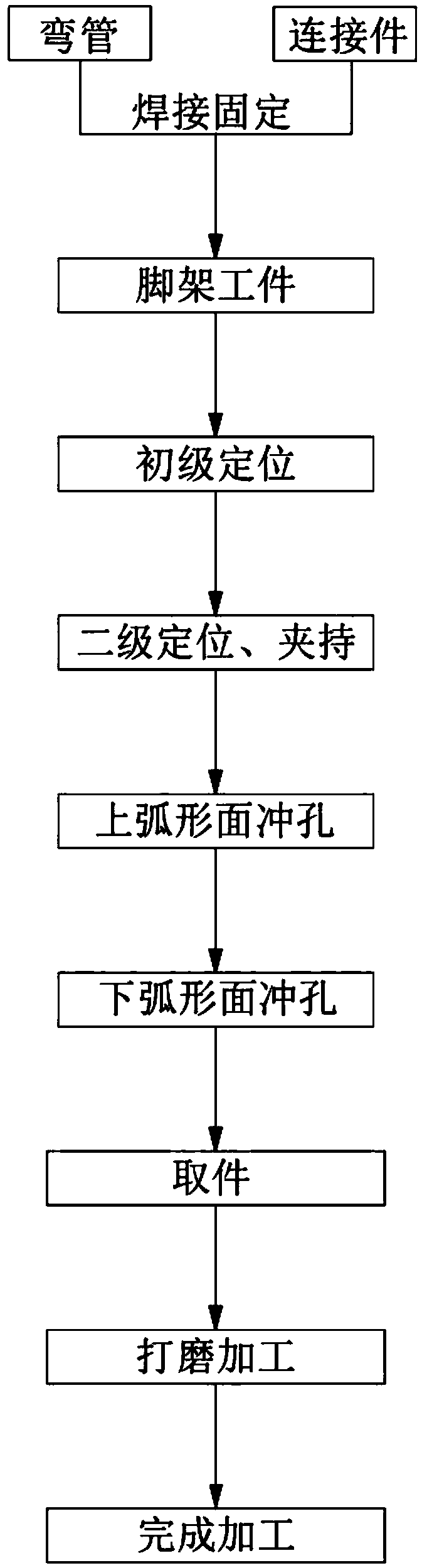
[0043] It is further explained that, because the elbow 11 is U-shaped, its shape is not easy to locate. Therefore, by adjusting the order of the processing steps of the tripod workpiece 1, the welding process steps of the elbow 11 and the connecting piece 12 are advanced to the time when the elbow 11 punches. Before the hole processing step, use the elbow 11 and the connecting piece 12 to weld the tripod workpiece 1, and then use the connecting piece 12 as the positioning coordinates to punch t...
Embodiment 2
[0066] Figure 4 It is a structural representation of a tripod workpiece punching die of the present invention; as Figure 4 As shown, the parts that are the same as or corresponding to those in Embodiment 1 use the reference numerals corresponding to Embodiment 1. For the sake of simplicity, only the differences from Embodiment 1 will be described below. This embodiment two and figure 1 The difference of the shown embodiment one is:
[0067] Such as Figure 4 , Figure 5 and Figure 6 Shown, a kind of tripod workpiece punching die comprises:
[0068] The upper mold assembly 2, the upper mold assembly 2 includes an upper mold base 21, the front end of the upper mold base 21 is symmetrically provided with a first positioning groove 211, and the lower end of the upper mold base 21 is connected with an upper splint 22; The two sides of the upper splint 22 are provided with second positioning grooves 221 corresponding to the positions of the first positioning grooves 211, an...
Embodiment approach
[0089] Such as Figure 10 and Figure 11 As shown, as a preferred embodiment, the lower mold assembly 3 also includes:
[0090] Lower mold base 33, described lower mold base 33 is positioned at the below of described lower mold bottom plate 31, and it is fixedly connected with this lower mold bottom plate 31;
[0091] A shaft sleeve 34, the shaft sleeve 34 is symmetrically arranged on both sides of the rear end of the bottom mold bottom plate 31, which is arranged corresponding to the guide shaft 24;
[0092] A plurality of lower optical axes 35, the lower optical axes 35 are arranged at the four corners of the bottom plate 31 of the lower mold;
[0093] The lower floating block 36, the lower floating block 36 is symmetrically arranged on both sides above the bottom plate 31 of the lower mold, and the lower floating block 36 slides vertically along the lower optical axis 35, and the middle part of the lower end is provided with a lower clip The holding bayonet 361, the lowe...
PUM
 Abstract
Description
Claims
Application Information
 - R&D Engineer
- R&D Manager
- IP Professional
- Industry Leading Data Capabilities
- Powerful AI technology
- Patent DNA Extraction
Browse by: Latest US Patents, China's latest patents, Technical Efficacy Thesaurus, Application Domain, Technology Topic, Popular Technical Reports.
© 2024 PatSnap. All rights reserved.Legal|Privacy policy|Modern Slavery Act Transparency Statement|Sitemap|About US| Contact US: help@patsnap.com