A punching die for tripod workpiece

A workpiece and punching technology, which is applied in the field of punching dies for tripod workpieces, can solve problems such as low work efficiency, difficulty in bending tube positioning, and easy to produce errors, and achieve the effects of good automation, high work efficiency and novel structure

Active Publication Date: 2018-07-06
ZHEJIANG LIFAN FURNITURE
View PDF1 Cites 0 Cited by
  • Summary
  • Abstract
  • Description
  • Claims
  • Application Information

AI Technical Summary

Problems solved by technology

[0002] In the process of furniture production and processing, it is inevitable to use working pipe workpieces, such as round tube supports, square tube supports and tripod workpieces, etc., and in the process of processing tripod workpieces, it is necessary to The arc-shaped side of the bracket workpiece is punched, and the traditional processing method is to use a punching tool to punch the arc-shaped surface of one side of the elbow before the elbow and the connector are welded to form an elbow tripod. After turning the elbow over, punch holes on the arc surface on the other side, but this processing method is not easy to locate the elbow, the work efficiency is low, and the punching holes on the upper and lower arc surfaces are inconsistent, which is easy to cause errors
[0003] In the Chinese patent with the patent number CN205362364U, a U-shaped tube punching die for newsstands is disclosed, including an upper mold unit and a lower mold unit, which can realize reliable positioning of the U-shaped tube during the punching process and improve Drilling efficiency and drilling accuracy, but the U-shaped tube punching die for newspaper kiosks cannot be applied to the tripod workpiece, and due to the shape of the elbow of the tripod workpiece, effective positioning cannot be performed, which can easily cause deviations in punching

Method used


Image

  • A punching die for tripod workpiece
  • A punching die for tripod workpiece
  • A punching die for tripod workpiece

Examples


Embodiment

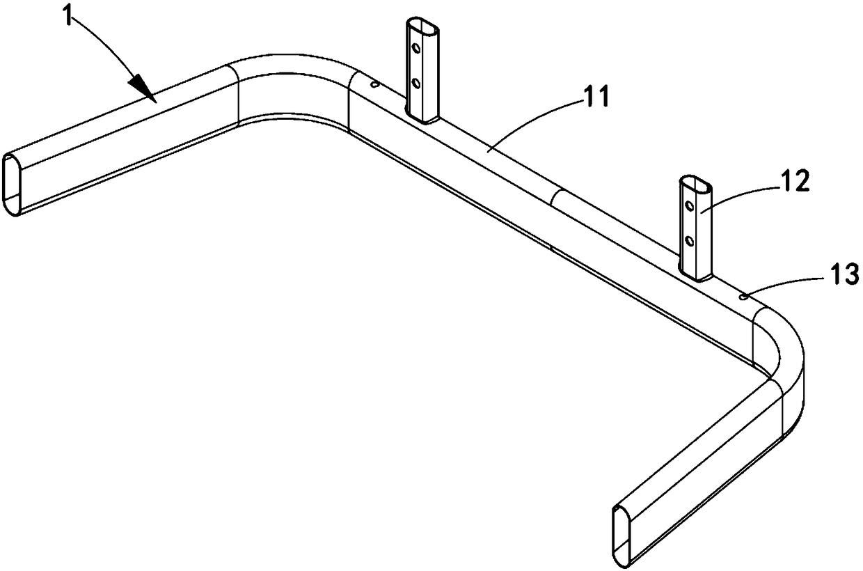
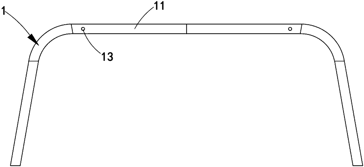
[0046] Such as figure 1 , figure 2 , image 3 , Figure 4 and Figure 5 As shown, a punching die for a tripod workpiece, the tripod workpiece 1 includes an elbow body 11, and connectors 12 and connecting holes 13 symmetrically arranged on both sides of the elbow body 11, and the connecting holes 13 are arranged on the The outside of the connector 12 includes:

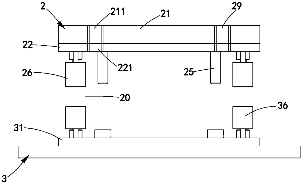
[0047] The upper mold assembly 2, the upper mold assembly 2 includes an upper mold base 21, the front end of the upper mold base 21 is symmetrically provided with a first positioning groove 211, and the lower end of the upper mold base 21 is connected with an upper splint 22; The two sides of the upper splint 22 are provided with second positioning grooves 221 corresponding to the positions of the first positioning grooves 211, and upper punches 23 are symmetrically arranged at both ends of the upper splint 22, and the upper ends of the upper punches 23 are aligned with the upper ends of the upper splint 22. The u...


PUM


Abstract

The invention discloses a floor stand workpiece punching die which comprises an upper die component and a lower die component, wherein first positioning grooves and second positioning groove coinciding with the first positioning grooves are formed in the upper die component. According to the floor stand workpiece punching die, the first positioning grooves and the second positioning groove are symmetrically formed in two sides of the front end of an upper die base of the upper die component and in two sides of the front end of an upper clamping plate of the upper die component and are used to effectively position a floor stand workpiece to solve the technical problem about accurate positioning in punching the floor stand workpiece; and then upper punching pins in the upper die component and lower punching pins in the lower die component realize synchronous punching of two arc-shaped side surfaces of the floor stand workpiece by virtue of assembly of the upper die component and the lower die component, the punching accuracy of the floor stand workpiece is guaranteed, and the working efficiency is improved.

Description

technical field [0001] The invention relates to the technical field of punching parts for furniture manufacturing, in particular to a punching die for tripod workpieces. Background technique [0002] In the process of furniture production and processing, it is inevitable to use working pipe workpieces, such as round tube supports, square tube supports and tripod workpieces, etc., and in the process of processing tripod workpieces, it is necessary to The arc-shaped side of the bracket workpiece is punched, and the traditional processing method is to use a punching tool to punch the arc-shaped surface of one side of the elbow before the elbow and the connector are welded to form an elbow tripod. After the elbow is turned over, the arc surface on the other side is punched, but this processing method is not easy to locate the elbow, the work efficiency is low, and the punching holes on the upper and lower arc surfaces are inconsistent, and errors are easily generated. [0003] ...

Claims


Application Information

Patent Timeline
Patent Type & Authority Patents(China)
IPC IPC(8): B21D28/34B21D43/00
CPCB21D28/34B21D43/003
Inventor 王优杰王泽凡
Owner ZHEJIANG LIFAN FURNITURE
Why Eureka
Try Eureka