
Method for enhancing slurry cutting capability

A slurry and capacity technology, applied in stone processing equipment, fine working devices, manufacturing tools, etc., can solve problems affecting production efficiency, ingot scrapping, deep line marks on the surface of ingots, etc., to improve the high-quality rate of prescribing and square extraction efficiency, ensuring the ability to carry sand, and saving the cost of square extraction

Inactive Publication Date: 2017-08-11
YANGZHOU RONGDE NEW ENERGY TECH
View PDF6 Cites 0 Cited by
  • Summary
  • Abstract
  • Description
  • Claims
  • Application Information

AI Technical Summary

Problems solved by technology

Therefore, the squaring process using mortar steel wire cutoff has the following disadvantages: the surface of the ingot cannot be flat and consistent with conventional polycrystalline ingots and is often accompanied by protrusions such as hot spots and impurities, so that the entire ingot usually appears in the middle. The situation of high and low sides causes the slurry to wash from high to low, and it often loses quickly due to the difference in height as soon as it reaches the surface of the crystal ingot, and the mortar that actually reaches the inside of the crystal ingot and attaches to the steel wire is greatly reduced.
At the same time, once impurities or hard spots appear inside the crystal ingot, when the ability of steel wire to carry sand is insufficient, it is easy to cause wire breakage or deep line marks on the surface of the crystal ingot during the process of squaring the impurity-intensive area, resulting in The size of the crystal ingot after grinding is too small or even lead to the scrapping of the crystal ingot, which in turn leads to the waste of workshop capacity and raw materials, seriously affecting production efficiency

Method used


Image

  • Method for enhancing slurry cutting capability
  • Method for enhancing slurry cutting capability
  • Method for enhancing slurry cutting capability

Examples


Embodiment Construction

[0025] In order to enable those skilled in the art to better understand the technical solutions of the present invention, the present invention will be described in detail below in conjunction with the accompanying drawings and specific embodiments.

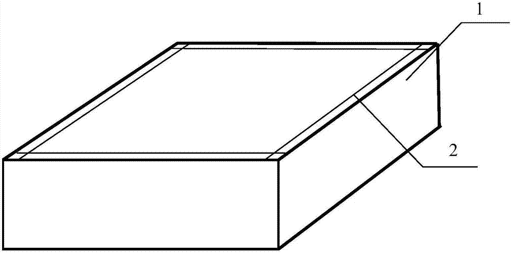
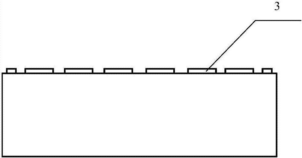
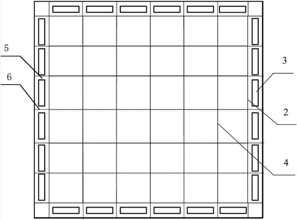
[0026] Such as Figure 1 to Figure 4 As shown, a method for enhancing the cutting ability of slurry provided by the present invention includes the following steps in turn: Step 1: before square opening, draw four edge reference lines 2 along the positions of the four edge edges on the upper surface of the ingot 1, and the edge edge The reference line 2 is the line drawn at the position of the ingot 1 close to the edge of the ingot before the square of the ingot is used to determine the cutting position of the ingot 1; Step 2: set up multiple interceptions along the length direction of the edge reference line 2 on its outer side Part 3 is used to block the slurry to prevent its loss and drain the slurry to the cutting wire mesh 4;...


PUM


Abstract

The invention discloses a method for enhancing slurry cutting capability. The method comprises the following steps: step 1, before squaring, drawing edge skin reference lines in the edge skin positions of the four edges of the upper surface of a crystal ingot; step 2, arranging a plurality of blocking components at the outer sides of the edge skin reference lines in the length direction of the edge skin reference lines for blocking slurry, preventing the slurry from running off and guiding the slurry to a cutting wire net; and step 3 which is optional, mechanically carrying out squaring. The method for reinforcing slurry cutting capability can realize slurry flow control, ensure that the slurry can continuously and uniformly reach the surface of the crystal ingot and ensure the sand carrying capability of a steel wire, so that the wire breaking rate of the steel wire is reduced, squaring losses are reduced, the squaring qualified rate and the squaring efficiency are increased, and the squaring cost is saved.

Description

technical field [0001] The invention relates to the field of square crystal ingots, in particular to a method for enhancing slurry cutting ability. Background technique [0002] At present, in the process of squaring polycrystalline ingots, the process method adopted is generally: cutting the entire crystal ingot by cutting steel wire with mortar, cutting diamond wire or band saw. [0003] In the conventional polycrystalline ingot square-cutting process, an important feature of using mortared steel wire to cut off is to ensure the flow rate of the mortar, which requires the slurry to be evenly distributed on the surface of the crystal ingot during the entire square-cutting process, accompanied by According to the cutting progress, the abrasive ability of the steel wire is guaranteed, and the steel wire still has good cutting ability after reaching the inside of the crystal ingot. Therefore, the squaring process using mortar steel wire cutoff has the following disadvantages:...

Claims


Application Information

Patent Timeline
Patent Type & Authority Applications(China)
IPC IPC(8): B28D5/04B28D5/00
CPCB28D5/045B28D5/007
Inventor 唐骏司天平惠昌军常传波
Owner YANGZHOU RONGDE NEW ENERGY TECH
Learn More