
air conditioner indoor unit

An air-conditioning indoor unit and air technology, which is applied in air-conditioning systems, mechanical equipment, space heating and ventilation, etc., can solve problems such as low temperature of reconciled air, discomfort of occupants, rise of reconciled air temperature, etc., to achieve comfortable and cool feeling, Easy and uniform temperature distribution

Active Publication Date: 2016-08-31
DAIKIN IND LTD
View PDF7 Cites 0 Cited by
  • Summary
  • Abstract
  • Description
  • Claims
  • Application Information

AI Technical Summary

Problems solved by technology

[0005] However, the temperature of the conditioned air at this stage is relatively low, such as blowing directly to the front of the person will cause discomfort to the occupants, so it is not preferred
[0006] On the other hand, the temperature of the conditioned air rises after the room temperature stabilizes, and the condition that the conditioned air does not reach people at all cannot satisfy the desire of the occupants who seek a cool feeling.

Method used


Image

  • air conditioner indoor unit
  • air conditioner indoor unit
  • air conditioner indoor unit

Examples


Embodiment Construction

[0047] Hereinafter, embodiments of the present invention will be described with reference to the drawings. In addition, the following embodiments are specific examples of the present invention, and do not limit the technical scope of the present invention.

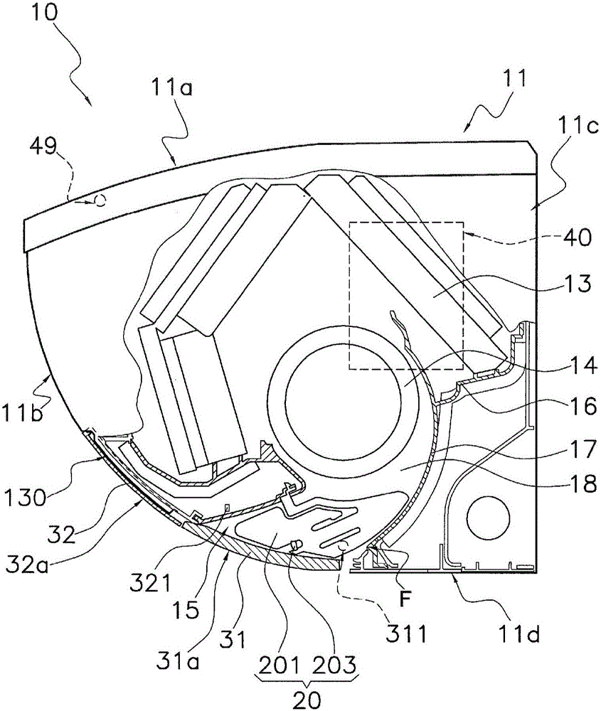
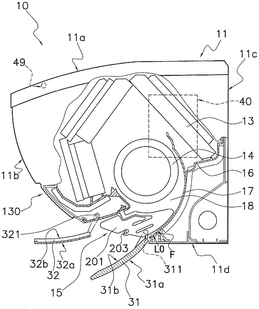
[0048] (1) Structure of the air conditioner indoor unit 10

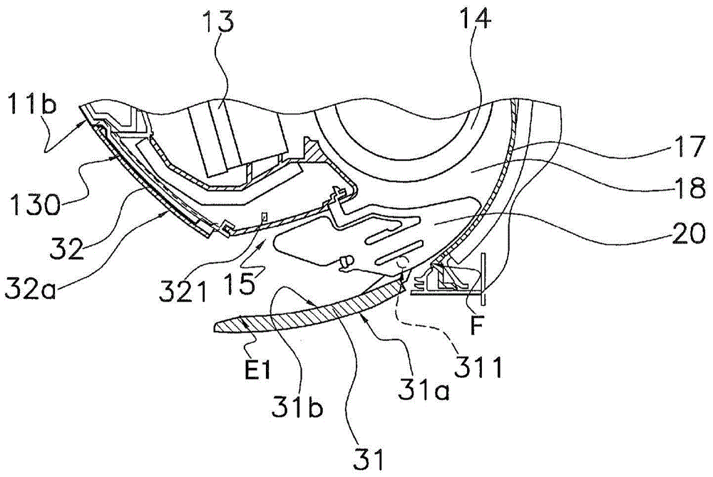
[0049] figure 1 It is a cross-sectional view of the air conditioner indoor unit 10 when the operation is stopped according to the embodiment of the present invention. in addition, figure 2It is a sectional view of the air conditioner indoor unit 10 during operation. exist figure 1 and figure 2 Among them, the air conditioner indoor unit 10 is a wall-mounted air conditioner indoor unit, and is equipped with a main body casing 11 , an indoor heat exchanger 13 , an indoor fan 14 , a bottom frame 16 and a control unit 40 .

[0050] The main body casing 11 has a top surface 11a, a front panel 11b, a back panel 11c, and a lower horizontal plate 11d, and accommo...


PUM


Abstract

Provides an air conditioner indoor unit that prevents blowing of air to occupants at the initial stage of cooling operation, and gives occupants a feeling of coolness after the room temperature stabilizes. In the air conditioner indoor unit (10), when the room temperature (Tr) is not within the target temperature range (Ts±a) based on the set temperature (Ts), the upper airflow mode is performed so that the airflow reaches every corner of the room. Also, when the room temperature (Tr) falls within the target temperature range, the temperature of the conditioned air also rises, and thus the up and down wind direction mode is executed, thereby making it possible to blow the wind to the occupants and provide a cool feeling.

Description

technical field [0001] The invention relates to an air conditioner indoor unit. Background technique [0002] Usually, in the initial stage of cooling operation, the temperature distribution in the room becomes uneven. In order to solve this problem, for example, the air conditioner described in Patent Document 1 (Japanese Patent Application Laid-Open No. 2004-108652 ) blows conditioned air forward and downward with a "strong" air volume, so that the air flow reaches all corners of the room. [0003] Summary of the invention [0004] The problem to be solved by the invention [0005] However, the temperature of the conditioned air at this stage is relatively low, and it is not preferable to blow down directly to the front of the occupants because it will cause discomfort to the occupants. [0006] On the other hand, after the room temperature stabilizes, the temperature of the conditioned air rises, and the condition that the conditioned air does not reach people at all c...

Claims


Application Information

Patent Timeline
Patent Type & Authority Patents(China)
IPC IPC(8): F24F11/02F24F13/08
CPCF24F11/79F24F1/0047F24F1/0011F24F2221/28F24F11/30F24F2110/10F24F11/65
Inventor 森隆滋藤冈裕记仲田贵裕松原笃志
Owner DAIKIN IND LTD
Learn More