
Belt sander workbench convenient for loading and unloading

A belt machine and workbench technology, which is applied to belt grinders, manufacturing tools, grinding racks, etc., can solve problems such as high labor intensity, achieve the effects of reducing labor intensity, ensuring effective transmission, and easy operation

Pending Publication Date: 2017-08-11
QUANYOU FURNITURE
View PDF12 Cites 1 Cited by
  • Summary
  • Abstract
  • Description
  • Claims
  • Application Information

AI Technical Summary

Problems solved by technology

[0005] The object of the present invention is to provide a workbench for the abrasive belt machine that is convenient for loading and unloading materials in view of the problem that the workpiece needs to be moved in and out of the above-mentioned abrasive belt machine and the labor intensity is high.

Method used


Image

  • Belt sander workbench convenient for loading and unloading
  • Belt sander workbench convenient for loading and unloading
  • Belt sander workbench convenient for loading and unloading

Examples


Embodiment 1

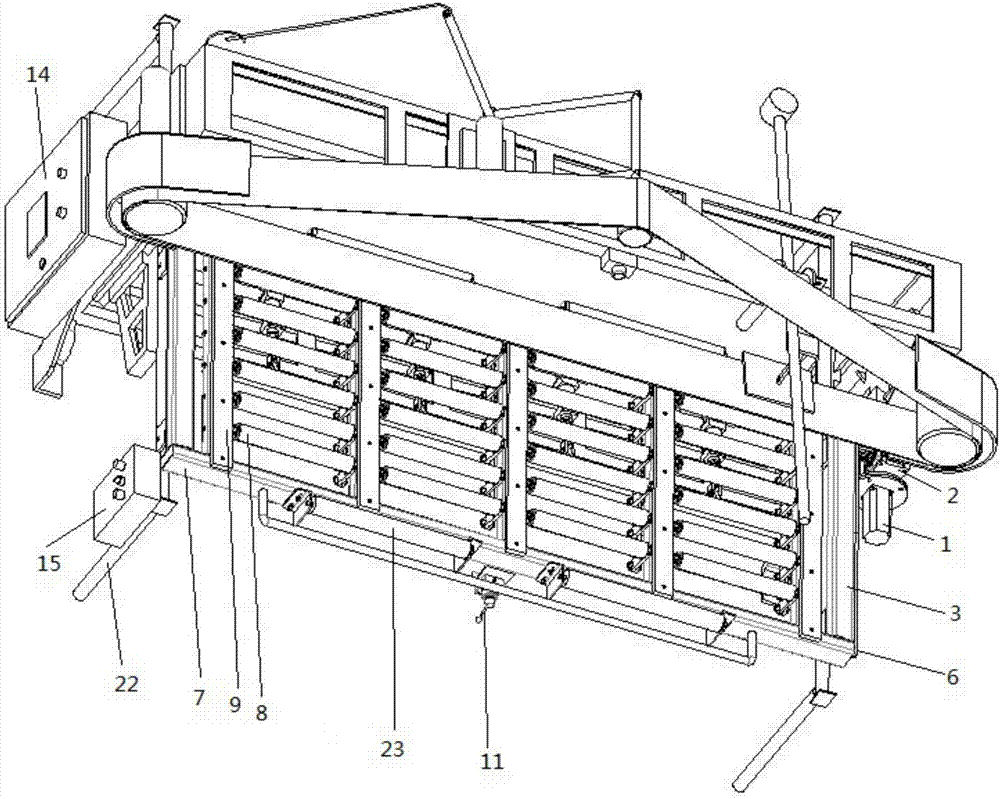
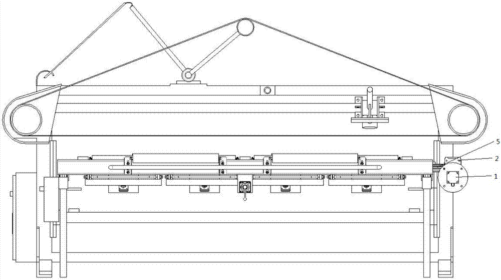
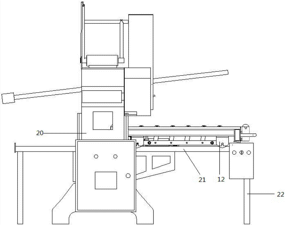
[0027] Such as Figure 1-4 As shown, an automatic walking abrasive belt machine for loading and unloading materials includes an abrasive belt, a motor, a pulley and a transmission device connecting the motor and the pulley. The motor drives the pulley through the transmission device, and the pulley drives the abrasive belt to operate. It also includes Frame 20, the workbench that is arranged on the abrasive belt below, workbench comprises the workbench 3 and reciprocating operation device that are convenient to loading and unloading.

[0028] The worktable 3 comprises a rough-surfaced table frame 7, a driving device 4 and a transmission device. Several lifting rollers 8 are installed in the table frame 7, and the driving device 4 drives the lifting roller 8 to lift through the transmission device.

[0029] The reciprocating operation device includes a servo motor 1, a travel transmission device, a pulley device and a control device for supporting the reciprocating travel of th...

Embodiment 2

[0033] Such as figure 1 As shown, further optimized on the basis of the workbench described in Embodiment 1, the loading and unloading edges of the table frame 7 are uniformly provided with some unloading rollers 23, and the unloading rollers 23 are higher than the table frame 7.

[0034] In this embodiment, the unloading roller can effectively reduce the wear of the non-processing surface of the workpiece and the worktable during the loading and unloading process; when multiple abrasive belt machines are used online, the rolling connection between the abrasive belt machines is increased to facilitate The workpiece is pushed online; it has a further limit function when processing the workpiece.

Embodiment 3

[0036] Such as figure 1 As shown, it is further optimized on the basis of the workbench described in Embodiment 1. The table frame 7 is a frame structure, and the frame is divided into several parts by a plurality of partition plates 10. The two sides of the table frame 7 and A wear-resistant Bakelite 9 is arranged above the dividing plate 10 .

[0037] In this embodiment, the frame structure of the table top frame 7 is convenient for the installation of the lifting roller, and the wear-resistant bakelite 9 ensures the roughness of the table top frame surface and is durable.


PUM


Abstract

The invention discloses a belt sander workbench convenient for loading and unloading. The belt sander workbench comprises a workbench surface, the workbench surface comprises a workbench surface frame with the rough surface, driving devices and transmission devices, a plurality of lifting rollers are installed in the workbench surface frame, and the driving devices drive the lifting rollers to rise and fall through the transmission devices. According to the belt sander workbench convenient for loading and unloading, after the driving devices drive the lifting rollers to rise through the transmission devices, the lifting rollers make direct contact with a marble workpiece, the position of the workpiece is moved in a pushing mode, the workpiece can be conveniently placed or pushed off the workbench, and then the labor intensity of operators is effectively reduced; after the driving devices drive the lifting rollers to fall through the transmission devices, the workbench surface frame makes direct contact with the marble workpiece, and then the relative static state between the workpiece and the workbench in the polishing process is guaranteed.

Description

technical field [0001] The invention belongs to the field of operation technology, and relates to a grinding and polishing device, in particular to a marble sanding belt machine. Background technique [0002] A belt machine is a mechanical device used to complete sanding work, and is widely used in processing industries such as wood, stone and metal. A belt sander can be used for polishing marble panels. Commonly used marble belt machines mainly include abrasive belts, frames, motors, pulleys, transmissions connecting the motors and pulleys, and workbenches. Usually, the workbench is set as a rough flat plate in order to facilitate the processing of the workpiece without sliding, with a single structure, and the following problems exist: [0003] 1. When loading and unloading, the operator needs to move the workpiece so that the workpiece can be placed in a suitable processing position on the workbench or leave the workbench, and the labor intensity of the operator is high...

Claims


Application Information

Patent Timeline
Patent Type & Authority Applications(China)
IPC IPC(8): B24B21/04B24B21/18B24B41/02B24B47/04
CPCB24B21/04B24B21/18B24B41/02B24B47/04
Inventor 张鸾军叶壮
Owner QUANYOU FURNITURE
Learn More