Shield structure for internal combustion engine

An internal combustion engine and shield technology, which is applied to the sealing device of the engine, mechanical equipment, engine components, etc., can solve the problems of increased weight, reduced compression ratio, and large size of the holding member 313, and achieves the goal of promoting light weight and improving sealing performance. Effect

Active Publication Date: 2017-08-08
TOYOTA BOSHOKU KK
View PDF8 Cites 4 Cited by
  • Summary
  • Abstract
  • Description
  • Claims
  • Application Information

AI Technical Summary

Problems solved by technology

[0005] However, in the technology disclosed in the aforementioned Japanese Patent Laid-Open No. 2015-102018, the oil seal 212 is held on the inner peripheral side of the through-hole 218 of the resin cover member 211, so it is difficult to satisfy the required size of the oil seal 212.
That is, the size of the resin cover member 211 tends to change in the radial direction of the crankshaft 203 due to the pressing force, heat, pressure, and creep of the oil seal 212, so that sufficient sealing performance of the oil seal 212 cannot be ensured.
Moreover, it is difficult to arrange the fastening bolts 214 around the crankshaft where parts such as sprockets and pulleys are concentrated.
In addition, another seal member 209 needs to be arranged between the fastening bolt 214 and the cover member 211, and therefore, there are restrictions on mounting.
[0006] Furthermore, in the technique disclosed in the above-mentioned Japanese Patent Application Laid-Open No. 2015-071996, it is a structure in which the outer periphery of the gasket 345 is compressed by bringing the metal holding member 313 into contact with the resin cover member 311 . Therefore, the dimensional tolerance increases and the difference in the compressibility of the gasket 345 becomes larger
Furthermore, although the washer 345 is arranged around the oil seal 312, the washer 345 is compressed by the fastening force of the fastening bolt 314 on the outer peripheral side, so the washer 345 cannot be compressed sufficiently, and the sealing performance of the washer 345 cannot be ensured. adequate sealing performance
Furthermore, when the resin shield member 311 is deformed by heat or pressure, the compressibility of the gasket 345 decreases, and there is a possibility of oil leakage.
Moreover, after the peripheral side of the resin shroud member 311 is fastened to the main body 302 of the internal combustion engine, the peripheral side of the metal holding member 313 is fastened to the main body 302 of the internal combustion engine. Therefore, the metal holding member 313 increase in size and weight

Method used


Image

  • Shield structure for internal combustion engine
  • Shield structure for internal combustion engine
  • Shield structure for internal combustion engine

Examples


Embodiment 1

[0066] (1) Engine guard structure

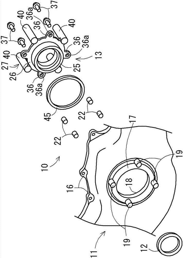
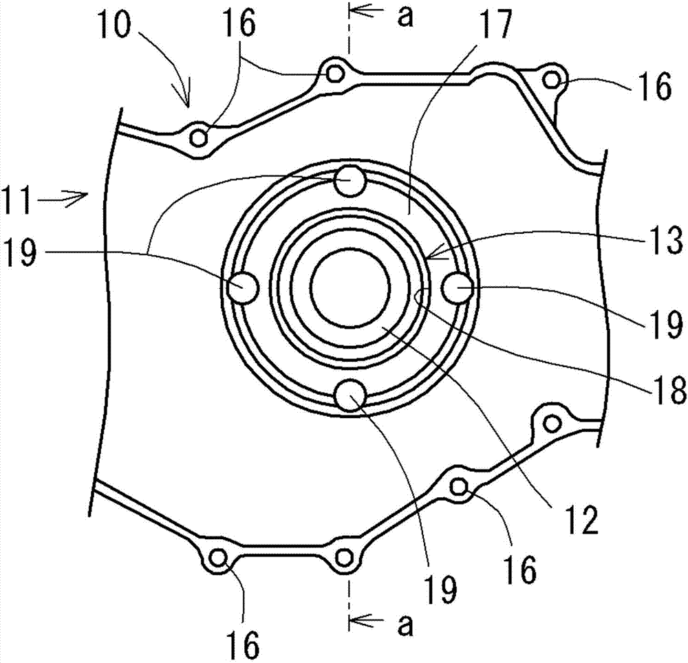
[0067] Such as figure 1 with figure 2 As shown, the engine shroud structure 10 of this embodiment is used to cover and protect the power transmission part 5 that transmits power from the crankshaft 3 to the camshaft of the engine. The shroud structure 10 includes: a shroud member 11 made of resin (for example, made of polyamide resin) capable of being attached to the engine main body 2 so as to cover the power transmission portion 5 ; and a holding member 13 , It is made of metal (such as aluminum alloy), and this holding member 13 holds the oil seal 12 that is crimped to the outer peripheral surface of the crankshaft 3 .

[0068] The shroud member 11 is formed in a box shape with one side open so as to be able to cover one side surface of the engine main body 2 . A plurality of fastening portions 16 that can be fastened to the engine main body 2 by fastening bolts 15 are provided on the opening end side of the shroud member 11 . And, ...

Embodiment 2

[0088]Next, the engine shroud structure of the second embodiment will be described. In addition, in the engine shroud structure of the second embodiment, the same reference numerals are attached to the structural parts substantially the same as those of the engine shroud structure 10 of the first embodiment described above, and detailed descriptions are omitted. Portions having substantially the same functions as those of the engine shroud structure 10 will be described with "A" appended to the same reference numerals.

[0089] (1) Engine guard structure

[0090] Such as Figure 11 As shown, the engine guard structure 10A of this embodiment has a guard member 11A made of resin (for example, made of polyamide resin, etc.), and the guard member 11A can be attached to the engine so as to cover the power transmission part 5 . Main body 2 ; and holding member 13A made of metal (for example, made of aluminum alloy) for holding oil seal 12 crimped on the outer peripheral surface of...

Embodiment 3

[0101] Next, the engine shroud structure of the third embodiment will be described. In addition, in the engine shroud structure of the third embodiment, the same reference numerals are attached to the structural parts substantially the same as those of the engine shroud structure 10 of the first embodiment described above, and detailed descriptions are omitted. Portions having substantially the same functions as those of the engine shroud structure 10 will be described with "B" attached to the same reference numerals.

[0102] (1) Engine guard structure

[0103] Such as Figure 14 As shown, the engine shroud structure 10B of this embodiment has: a shroud member 11B made of resin (for example, made of polyamide resin, etc.), and the shroud member 11B can be attached to the engine so as to cover the power transmission part 5 The main body 2 ; and a holding member 13B made of metal (for example, made of aluminum alloy) for holding the oil seal 12 crimped on the outer peripheral...


PUM


Abstract

The present invention provides a shield structure for an internal combustion engine. The shield structure of the internal combustion engine can be reduced in weight and can ensure sufficient sealing performance of the oil seal and the gasket.The shield structure of the internal combustion engine includes a shield member (11) which is made of resin and which can be attached to the main body (2) of the internal combustion engine in such a manner as to cover the power transmission portion (5); and a holding member (13) which is made of metal, and the holding member holds the oil seal (12) pressed against the outer peripheral surface of the crankshaft.Further, the holding member is engaged with the main body of the internal combustion engine so as to be able to be positioned in the axial direction of the crankshaft and in the plane direction orthogonal to the axial direction.Further, a gasket (45) sandwiched between the shroud member and the holding member so as to surround the crankshaft is fastened by the fastening bolt (37).

Description

technical field [0001] The present invention relates to a shroud structure of an internal combustion engine, and more specifically, to a shroud structure of an internal combustion engine for covering a power transmission portion that transmits power from a crankshaft to a camshaft of the internal combustion engine. Background technique [0002] As a conventional shroud structure of an internal combustion engine, a shroud structure that covers a power transmission portion (such as a timing chain, etc.) that transmits power from a crankshaft to a camshaft of the internal combustion engine is generally known. For example, if Figure 19 As shown, this shroud structure 110 includes a metal shroud member 111 that can be attached to the main body 102 of the internal combustion engine (for example, a cylinder block, etc.) so as to cover the power transmission unit 105 . Further, a through hole 118 for the crankshaft 103 is formed in the guard member 111 , and an oil seal 112 press-c...

Claims


Application Information

Patent Timeline
Patent Type & Authority Applications(China)
IPC IPC(8): F02F7/00
CPCF02F7/0021F02F7/0065F02F7/0085F02F2007/0041F01L1/022F01L1/024F01L1/026F01L2001/0537F02F7/0073F02F11/00F02F2007/0078F01L2301/00F01L1/02
Inventor 后藤达也
Owner TOYOTA BOSHOKU KK
Why Eureka
Try Eureka