
Acoustic vector sensor array space rotation solution coherence arrival angle estimation method

An acoustic vector sensor and space rotation technology, applied in the field of signal processing, can solve the problems of increasing the array beam width, reducing the array aperture, reducing the parameter estimation accuracy, etc., to achieve high spatial resolution, expanding the scope of application, high direction finding The effect of precision

Inactive Publication Date: 2017-08-01
XIDIAN UNIV
View PDF3 Cites 8 Cited by
  • Summary
  • Abstract
  • Description
  • Claims
  • Application Information

AI Technical Summary

Problems solved by technology

At present, the methods of decoherence can be roughly divided into two categories, one is the dimensionality reduction method represented by the spatial smoothing and matrix reconstruction method, and the other is the non-dimensionality reduction method represented by the focusing and virtual transformation method. However, there are still some limitations and deficiencies. The non-dimensionality reduction algorithm represented by focusing processing has high computational complexity; the dimensionality reduction method represented by spatial smoothing reduces the array aperture and increases the array size. beamwidth, which reduces the parameter estimation accuracy
And spatial smoothing is generally only suitable for uniform arrays, which severely limits the scope of application of the method

Method used


Image

  • Acoustic vector sensor array space rotation solution coherence arrival angle estimation method
  • Acoustic vector sensor array space rotation solution coherence arrival angle estimation method
  • Acoustic vector sensor array space rotation solution coherence arrival angle estimation method

Examples


Embodiment Construction

[0024] In order to make the above and other objects, features and advantages of the present invention more apparent, the following specifically cites the embodiments of the present invention, together with the accompanying drawings, for a detailed description as follows.

[0025] figure 1 Shown is a schematic diagram of an acoustic vector sensor array according to an embodiment of the present invention. The acoustic vector sensor array of the present invention is composed of M array elements arbitrarily distributed on the x-axis, and the array elements are acoustic vector sensors with spatial co-point synchronous measurement of sound pressure and vibration velocity components in the directions of x-axis, y-axis and z-axis ; The distance between any two adjacent array elements is less than or equal to λ min / 2, λ min is the minimum wavelength of the incident acoustic wave signal;

[0026] refer to figure 2 , the steps of the decoherent angle-of-arrival estimation method of...


PUM


Abstract

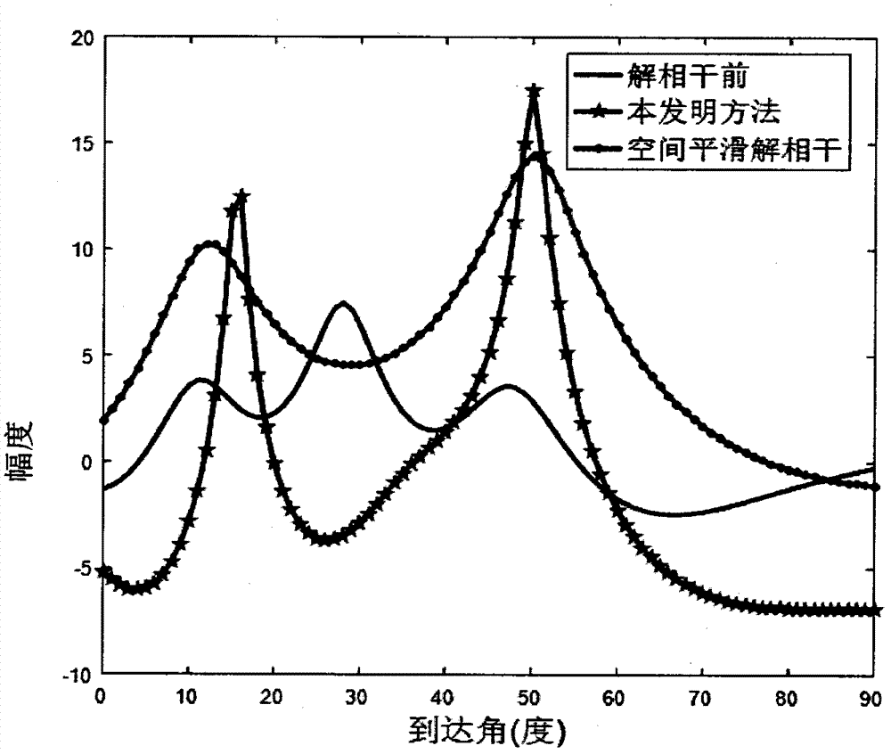
The invention provides an acoustic vector sensor array space rotation solution coherence arrival angle estimation method. An array receives K coherence narrowbands and a stationary far-field signal. The single-shot snapshot output data of all elements are acquired through a receiving array. N-times snapshot data of the array are measured. The orthogonal vector characteristic of an acoustic vector sensor is fully used. The acoustic vector sensor array is divided into four sub-arrays of an acoustic pressure sub-array, an x-axis vibration velocity sub-array, a y-axis vibration velocity sub-array and a z-axis vibration velocity sub-array. The signal covariance matrix rank is acquired through sub-array processing, so as to acquire a data covariance matrix after solution coherence. A noise space is acquired through the data covariance matrix after solution coherence. A noise subspace is used to construct a MUSIC spatial spectrum. The estimated value of an arrival angle is acquired by searching the one-dimensional MUSIC peak of an angular domain. Compared with a spatial smooth de-coherence method, the method provided by the invention is applicable to a uniform linear array and a non-uniform linear array, is free of aperture loss, and has the advantages of higher spatial resolution, orientation accuracy and wide application range.

Description

technical field [0001] The invention belongs to the technical field of signal processing, in particular to a method for estimating the arrival angle of a coherent source of an acoustic vector sensor array. Background technique [0002] In practice, due to the multipath phenomenon, echo signal and human interference in the signal transmission process, the correlation signal source is very common, so the detection and estimation based on the correlation source is an important research topic of signal processing. When the incident signals are independent of each other, the subspace method has good parameter estimation performance, but if the incident signal is coherent, the subspace algorithm represented by MUSIC will fail. When the incident signal is a coherent signal, the dimensionality of the signal subspace will be smaller than the number of signal sources, and the signal subspace will spread to the noise subspace, which will cause the signal subspace and the noise subspace...

Claims


Application Information

Patent Timeline
IPC IPC(8): G01S3/80G01S11/14
CPCG01S3/8003G01S11/14
Inventor 王兰美廖桂生魏兵孙长征张艳艳代少玉
Owner XIDIAN UNIV
Learn More