
Bunsen burner type low-temperature plasma auxiliary burning device

A low-temperature plasma and assisted combustion technology, which is applied to gas fuel burners, burners, combustion methods, etc., can solve the problems of expensive microwave sources or nanosecond pulse sources, inability to fix the center electrode well, and complicated manufacturing processes, etc. problem, to achieve significant combustion-supporting effect, enhanced flame combustion, increased flame propagation speed and flame temperature

Active Publication Date: 2017-07-28
XI AN JIAOTONG UNIV
View PDF5 Cites 3 Cited by
  • Summary
  • Abstract
  • Description
  • Claims
  • Application Information

AI Technical Summary

Problems solved by technology

The plasma area generated by general devices is small, and the plasma with higher energy often faces the problem of high temperature. Therefore, arc discharge is prone to occur in a high-voltage environment, and the microwave source or nanosecond pulse source required by the most cutting-edge devices is also Expensive; (2) Matching of plasma reactor and burner structure
The flat electrode structure that is easy to diagnose is difficult to use as a burner, and the widely used center electrode structure faces disadvantages such as the center electrode cannot be fixed well and the manufacturing process is complicated.

Method used


Image

  • Bunsen burner type low-temperature plasma auxiliary burning device
  • Bunsen burner type low-temperature plasma auxiliary burning device
  • Bunsen burner type low-temperature plasma auxiliary burning device

Examples


Embodiment Construction

[0038] The present invention will be further described in detail below in conjunction with specific embodiments, so as to better understand the functions and characteristics of the present invention.

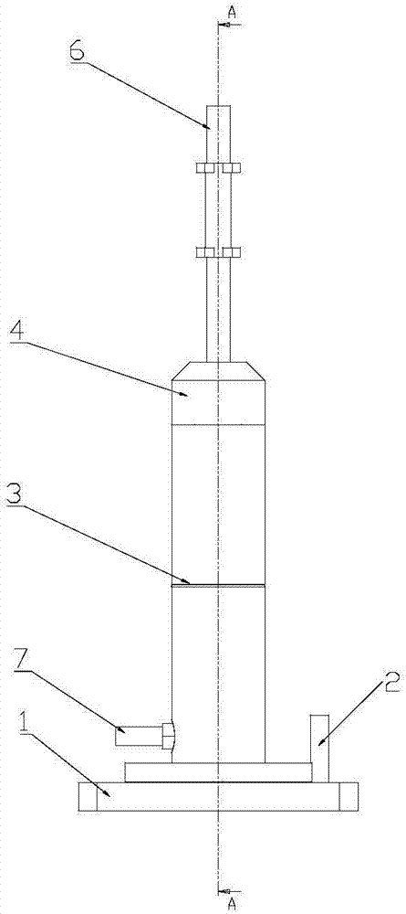
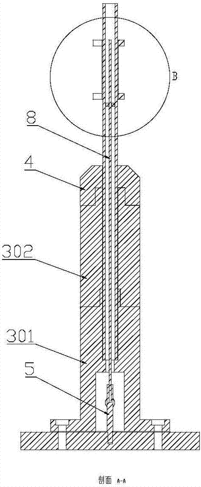
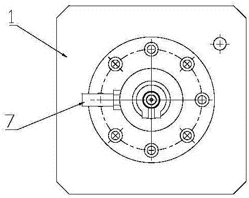
[0039] Such as Figure 1a to Figure 1d, a Bunsen burner type low-temperature plasma assisted combustion device provided by the present invention includes a base, a gas buffer unit and a plasma reaction unit; wherein the base includes a bottom plate 1 and a ground wire terminal 2 arranged on the bottom plate; the gas buffer The unit includes a fixed flange 3, a flange cap 4 and a fixed rod 5; the plasma reaction unit includes an outer electrode, an inner electrode 8 and a quartz glass tube 6; A connected gas collection chamber and a stepped hole are opened from bottom to top, and an air inlet 7 communicating with the gas collection chamber is provided on the side wall of the fixed flange 3, and the bottom of the quartz glass tube 6 is fixed at the stepped hole , the top protrude...


PUM

PropertyMeasurementUnit
Heightaaaaaaaaaa
Outer diameteraaaaaaaaaa
The inside diameter ofaaaaaaaaaa

Abstract

The invention relates to a Bunsen burner type low-temperature plasma auxiliary burning device. The Bunsen burner type low-temperature plasma auxiliary burning device comprises a base, a gas buffer unit and a plasma reaction unit, wherein the gas buffer unit comprises a fixed flange and a fixed rod; the plasma reaction unit comprises an outer electrode, an inner electrode and a quartz glass tube; the bottom of the fixed flange is fixed to the center of a bottom plate, a gas collection chamber and a stepped hole which are communicated are formed in the center of the fixed flange from bottom to top, and an air inlet which communicates with the gas collection chamber is formed in the side wall of the fixed flange; the bottom of the quartz glass tube is fixed to the stepped hole, and the top of the quartz glass tube protrudes to the outside of the fixed flange; the bottom of the fixed rod is fixed to the center of the bottom plate, and a flange cap sleeve is installed on the quartz glass tube and is connected to the top of the fixed flange; and the bottom of the inner electrode is fixed to the top of the fixed rod, and the outer electrode sleeves the quartz glass tube which is opposite to the inner electrode. The Bunsen burner type low-temperature plasma auxiliary burning device can be removed to replace and has the advantage of convenience in use and later maintenance. Low-temperature plasma which is generated by discharge is rich in various active particles, and an obvious strengthening effect is achieved on burning.

Description

[0001] Technical field: [0002] The invention belongs to the technical field of low-temperature plasma application, and in particular relates to a Bunsen burner type low-temperature plasma auxiliary combustion device. [0003] Background technique: [0004] In recent years, with the development of low-temperature plasma technology, the combustion-supporting technology based on low-temperature plasma has attracted the attention of scholars at home and abroad. Low-temperature plasma has a large number of active particles, which plays an important role in reducing ignition delay and improving combustion efficiency. Low-temperature plasma combustion-supporting technology has also become one of the hot issues studied by scholars from all over the world. [0005] However, people’s understanding of the combustion-supporting mechanism of low-temperature plasma is still unclear. The effect of non-thermal equilibrium plasma on combustion characteristics is an extremely complex physical ...

Claims


Application Information

Patent Timeline
IPC IPC(8): F23D14/08F23D14/46H01J27/16
CPCH01J27/16F23D14/08F23D14/46
Inventor 穆海宝虞春艳李平张冠军
Owner XI AN JIAOTONG UNIV
Learn More