
Portable outdoor floating power generation device and work method thereof

A power generation device and portable technology, which can be used in wind power generation, wind turbines in the same direction as the wind, and configurations for installing/supporting wind turbines. , to achieve the effect of light weight, improved power generation efficiency and high power generation efficiency

Active Publication Date: 2017-07-28
赣州市兴顺辉科技有限公司
View PDF6 Cites 1 Cited by
  • Summary
  • Abstract
  • Description
  • Claims
  • Application Information

AI Technical Summary

Problems solved by technology

[0002] In modern times, more and more people like outdoor sports, outdoor adventures, outdoor survival and camping, but people's lives are closely related to electricity. Most daily necessities need electric power, such as mobile phones, shavers, flashlights, searchlights, various Kitchen appliances, etc. It can be said that in modern times, in addition to food and water in the wild, the most important thing is electricity, but it is difficult to obtain electricity in the wild. If you carry a battery, it is not only heavy, but the key is that it cannot supply too much electricity continuously. Some field power generation equipment is generally solar power generation, which is not only large in size, heavy in weight, inconvenient to carry, but also low in power generation efficiency, especially in the wild jungle, it is difficult to meet the needs of field life

Method used


Image

  • Portable outdoor floating power generation device and work method thereof
  • Portable outdoor floating power generation device and work method thereof
  • Portable outdoor floating power generation device and work method thereof

Examples


Embodiment Construction

[0045] The present invention will be described in detail below in conjunction with the accompanying drawings and specific embodiments.

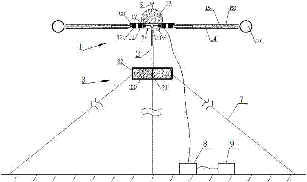
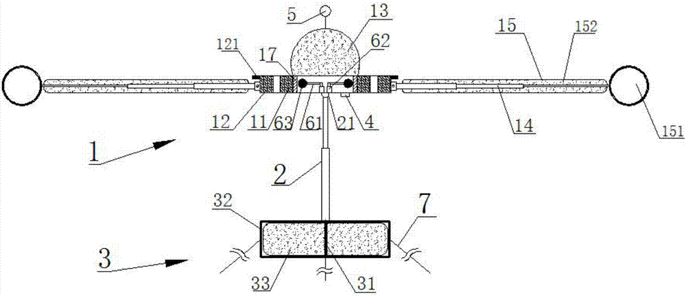
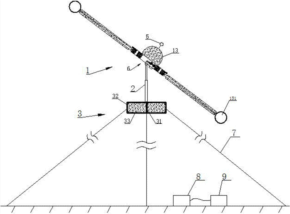
[0046] Such as Figures 1 to 3 As shown, a portable outdoor floating power generation device includes a power generation main body 1, a telescopic connecting rod 2 and a supporting round table 3 arranged in sequence from top to bottom; the supporting round table 3 is arranged horizontally, and the connecting rod 2 is arranged vertically; The power generation main body 1 includes a hollow cylindrical accommodation body 17 vertically arranged, an annular generator stator winding 11 fixedly sleeved outside the accommodation body 17, and an annular generator rotor 12 rotatably sleeved outside the generator stator winding 11; Through the relative rotation of the generator rotor 12 and the generator stator winding 11 , the generator stator winding 11 cuts the magnetic induction line to realize power generation; above the accommodating body 17 is conn...


PUM


Abstract

The invention relates to a portable outdoor floating power generation device and a work method thereof. The portable outdoor floating power generation device comprises a power generation main body, a telescopic connecting rod and a supporting round table which are sequentially arranged from top to bottom; the supporting round table is horizontally arranged, the connecting rod is vertically arranged, the power generation main body comprises a vertical containing body in a hollow cylindrical shape, an annular power generation stator winding fixedly arranged outside the containing body in a sleeving manner and an annular power generation rotor rotatably arranged outside the power generation stator winding in a sleeving manner, a first inflation bag which can float through inflation is connected to the upper portion of the containing body, the outer circumference of the power generation rotor is connected with multiple horizontal telescopic rods which are sleeved with second strip-shaped inflation bags which can float through inflation, one end of each second inflation bag is fixed to the root of the corresponding telescopic rod, and the other end of each second inflation bag is fixed to the tail end of the corresponding telescopic rod; the tail ends of the telescopic rods are located outside the inflation bags and are further fixedly provided with bowl-shaped air facing parts; the concave arc faces of the air facing parts face the tangent direction of the outer circumference of the containing body.

Description

technical field [0001] The invention relates to a portable outdoor floating power generation device and a working method thereof, belonging to the field of outdoor equipment. Background technique [0002] In modern times, more and more people like outdoor sports, outdoor adventures, outdoor survival and camping, but people's lives are closely related to electricity. Most daily necessities need electric power, such as mobile phones, shavers, flashlights, searchlights, various Kitchen appliances, etc. It can be said that in modern times, in addition to food and water in the wild, the most important thing is electricity, but it is difficult to obtain electricity in the wild. If you carry a battery, it is not only heavy, but the key is that it cannot supply too much electricity continuously. Some field power generation equipment is generally solar power generation, which is not only large in size, heavy in weight, inconvenient to carry, but also low in power generation efficienc...

Claims


Application Information

Patent Timeline
Patent Type & Authority Applications(China)
IPC IPC(8): F03D9/11F03D1/06F03D7/04F03D13/20
CPCF03D7/0204F03D7/042F05B2240/922F05B2270/321F05B2270/602Y02E10/72Y02E70/30
Inventor 苏福来
Owner 赣州市兴顺辉科技有限公司
Learn More