


Quick Research
Generate reliable direction feasibility study reports for your R&D in just a few steps.

Technical Q&A
Discover and master advanced knowledge NOW. Basics, ideas, possibilities, all at once.

Find Solutions
As an expert in R&D theories, this can generate solutions to your technical problems instantly.

Evaluate Feasibility
Analyze your overall solution with one click, know your potential R&D risks in advance.

Monitor Landscape
Get weekly tech updates, stay abreast of the latest tech innovations and key insights.
High-efficiency gas purification tower and gas treating system
A gas treatment and gas purification technology, applied in the fields of desulfurization, dust removal and fog removal, can solve the problems of low flue gas purification efficiency, achieve the effects of avoiding secondary entrainment, reducing costs and improving purification efficiency
- Summary
- Abstract
- Description
- Claims
- Application Information
AI Technical Summary
Problems solved by technology
Method used
Image

Examples
Embodiment 1
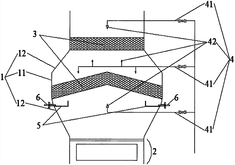
[0047] This embodiment provides a gas processing tower, such as Figure 1 to Figure 8 shown, including:
[0048] tower body 1;
[0049] Packing layer 3, straddling the tower body 1, at least one layer is arranged, and its side walls are connected with the surrounding inner walls of the tower body 1;
[0050] The pipeline spraying system 4 is arranged inside the tower body 1, and it is equipped with a spray head 42 arranged towards the packing layer 3;
[0051] It is characterized in that the packing layer 3 includes a wire mesh layer and a number of bulk fillers packed inside the wire mesh layer, preferably spherical packing.
[0052] In the above-mentioned gas treatment tower, a packing layer 3 is arranged in the tower body 1. When the flue gas passes through the packing layer 3, it can fully contact with the spherical packing, effectively derotation and dispersing the swirling flue gas, and the mist entrained by the flue gas and The dust is effectively and quickly absorbe...
Embodiment 2
[0079] In this embodiment, the original baffle defogging system of the upper half of the non-amplified section flue gas ammonia method wet desulfurization tower with a diameter of 8 meters of a 3×75 ton / hour thermoelectric coal-fired boiler has been modified.
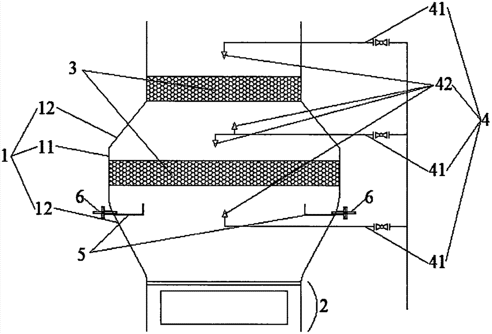
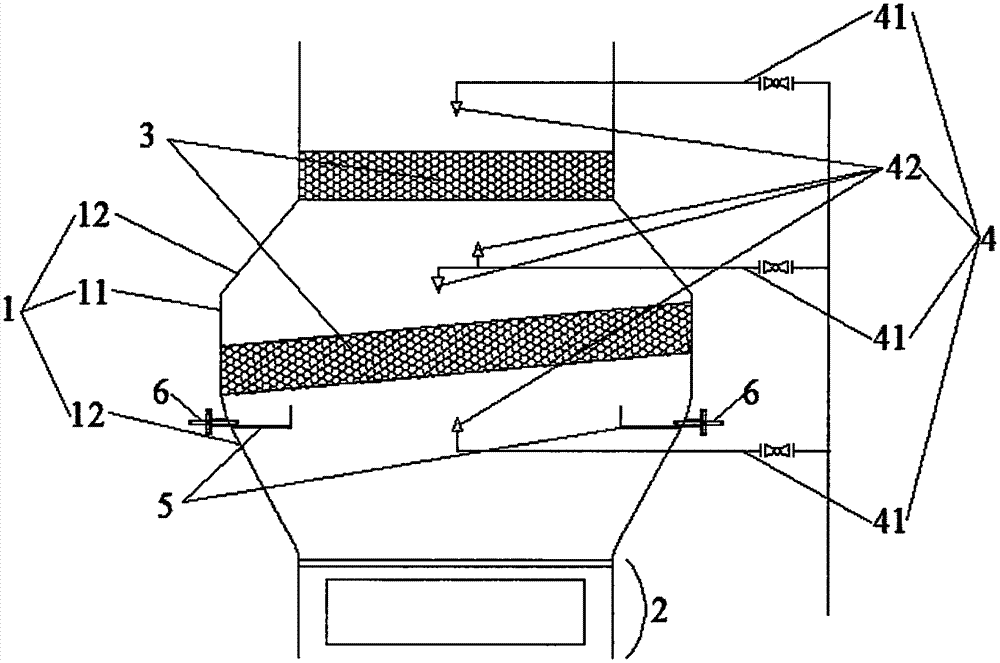
[0080] Among them, the numbers of different experimental conditions of the flue gas purification tower are 1#, 2#, 3#, 4#, 5#, 6#. Such as Figure 7 As shown, the packing layer of 1# has only one layer and is set at the cylindrical tower body. The inner diameter of the tower is 8 meters, and the diameter of the spherical packing is Φ50mm. To prevent clogging, 316L stainless steel wire mesh porous hollow body spherical packing is used. Such as Figure 8 As shown, 2#, 3#, 4#, 5#, and 6# have two layers of packing layers respectively, the inner diameter of the tower is 8 meters, the lower layer is a spherical packing layer filled with a height of 800mm, and the upper layer is a baffle with a height of 200mm7 , A spherica...
PUM
| Property | Measurement | Unit |
|---|---|---|
| Outer diameter | aaaaa | aaaaa |
| Height | aaaaa | aaaaa |
| Diameter | aaaaa | aaaaa |
Abstract
Description
Claims
Application Information
 - R&D Engineer
- R&D Manager
- IP Professional
- Industry Leading Data Capabilities
- Powerful AI technology
- Patent DNA Extraction
Browse by: Latest US Patents, China's latest patents, Technical Efficacy Thesaurus, Application Domain, Technology Topic, Popular Technical Reports.
© 2024 PatSnap. All rights reserved.Legal|Privacy policy|Modern Slavery Act Transparency Statement|Sitemap|About US| Contact US: help@patsnap.com