A multiprocessor permanent magnet brushless DC motor joint speed regulation system and method

A permanent magnet brushless DC and brush DC motor technology, which is applied in the control system, electronically commutated motor control, excitation or armature current control, etc., can solve the problem that the signal transmission cable of the position sensor is easily disturbed by the external environment and increases The size and cost of the brushless DC motor, the single detection method of the rotor position signal, etc., achieve the effect of increasing the reliability of speed regulation and operation safety, facilitating popularization and use, and flexible operation mode

Inactive Publication Date: 2019-11-26
LANZHOU UNIVERSITY OF TECHNOLOGY
View PDF8 Cites 0 Cited by
  • Summary
  • Abstract
  • Description
  • Claims
  • Application Information

AI Technical Summary

Problems solved by technology

[0003] The existing brushless DC motor speed control system and method have the following defects and deficiencies: (1) The position sensor is used to detect the rotational position of the rotor, which further increases the volume and cost of the brushless DC motor, and the signal transmission cable of the position sensor is easily affected by the external environment. (2) The non-position rotor position signal detection method is single, only using the back EMF pulse method or the stator terminal voltage analog acquisition method, and does not combine the digital and analog methods to judge the rotor. Rotation position; (3) Only one processor is used for drive control without combining the advantages of multi-processing joint operation. If the control board processor fails, the motor cannot run continuously and stably; (4) The motor drive control bridge uses a single bridge operation In this way, when the power electronic device on any bridge wall fails, the brushless DC motor needs to be shut down immediately for maintenance

Method used


Image

  • A multiprocessor permanent magnet brushless DC motor joint speed regulation system and method
  • A multiprocessor permanent magnet brushless DC motor joint speed regulation system and method

Examples


Embodiment Construction

[0042] The present invention will be further described in detail below in conjunction with specific embodiments, which are explanations of the present invention rather than limitations.

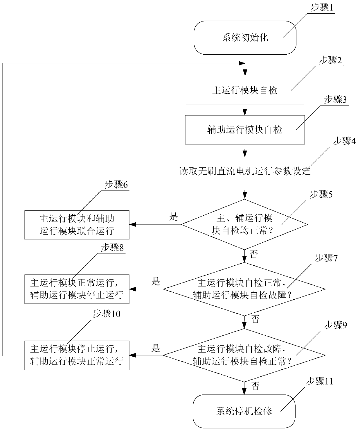
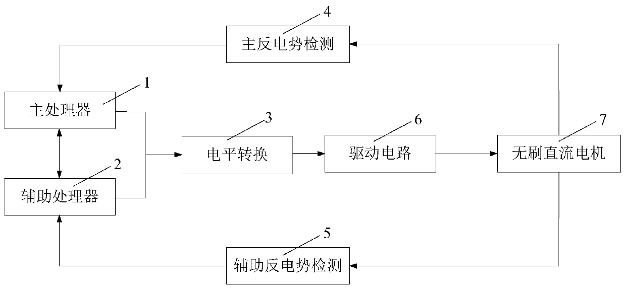
[0043] Such as figure 1 and figure 2 As shown, a multiprocessor permanent magnet brushless DC motor combined speed control system includes a brushless DC motor 7, and also includes a main processor module 1, an auxiliary processor module 2, a level conversion module 3, and a main back EMF detection Module 4, auxiliary back EMF detection module 5 and drive circuit module 6; wherein, the main processor module 1 and the auxiliary processor module 2 are used to collect the rotor position of the brushless DC motor 8, and pass the detected rotor rotation position Respectively output digital PWM signals for controlling the rotational speed of the brushless DC motor 8, the communication end of the main processor module 1 and the communication end of the auxiliary processor module 2 are connected wi...


PUM


Abstract

The invention relates to a multiprocessor permanent-magnet brushless DC motor combined speed regulation system and method. The speed regulation of a brushless DC motor is controlled by a system which comprises a main operation module and an auxiliary operation module, wherein the main operation module and the auxiliary operation module can interact with each other, and are connected in parallel. The method enables a rotor of the brushless DC motor to achieve the no-position detection without an additional rotor detection module through a counter electromotive force method for main counter electromotive force detection and a stator end voltage analog collection method for auxiliary counter electromotive force detection, and further reduces the speed regulation cost and size of the brushless motor. Moreover, the above two methods cooperate for the detection of the position of a motor rotor, thereby guaranteeing the normal phase change of the brushless motor, and improving the precision of a processor decision making basis and the position detection of the rotor. When any one detection unit has a fault, the operation of the brushless motor is not affected. Meanwhile, the processors in the main operation module and the auxiliary operation nodule complement the rotor position detection. The system and method are high in detection precision of the position of the rotor, are good in control and speed regulation stability, and is flexible in operation mode.

Description

technical field [0001] The invention relates to the technical field of brushless DC motor speed regulation, in particular to a multiprocessor permanent magnet brushless DC motor combined speed regulation system and method. Background technique [0002] With the rapid development of power electronics technology and devices, brushless motor BLDC gradually replaces traditional brushed motors with its advantages of no carbon brush wear, no commutation sparks, low noise, low maintenance costs, high operating efficiency and long service life. And it is widely used in emerging technology fields such as home appliances, model airplanes, and electric vehicles. The brushless motor must judge the rotation position of the rotor when adjusting the speed. The controller uses the rotation position fed back by the rotor to commutate according to the set control strategy, so that the motor can rotate continuously and reliably in each operation cycle. In the field of position sensor detectio...

Claims


Application Information

Patent Timeline
Patent Type & Authority Patents(China)
IPC IPC(8): H02P7/28H02P6/182
CPCH02P6/182H02P7/28
Inventor 杨沛豪刘向辰蔺健王晓兰寇水潮
Owner LANZHOU UNIVERSITY OF TECHNOLOGY
Why Eureka
Try Eureka