
Method of preventing vortex slag entrapment through argon blowing in steel ladle tapping process

A technology of tapping process and ladle, applied in the direction of casting melt containers, manufacturing tools, metal processing equipment, etc., can solve the problems of disturbing the flow field distribution caused by the vortex, and achieve the advantages of homogenization, low cost and high yield rate effect

Inactive Publication Date: 2017-07-25
NORTHEASTERN UNIV
View PDF7 Cites 12 Cited by
  • Summary
  • Abstract
  • Description
  • Claims
  • Application Information

AI Technical Summary

Problems solved by technology

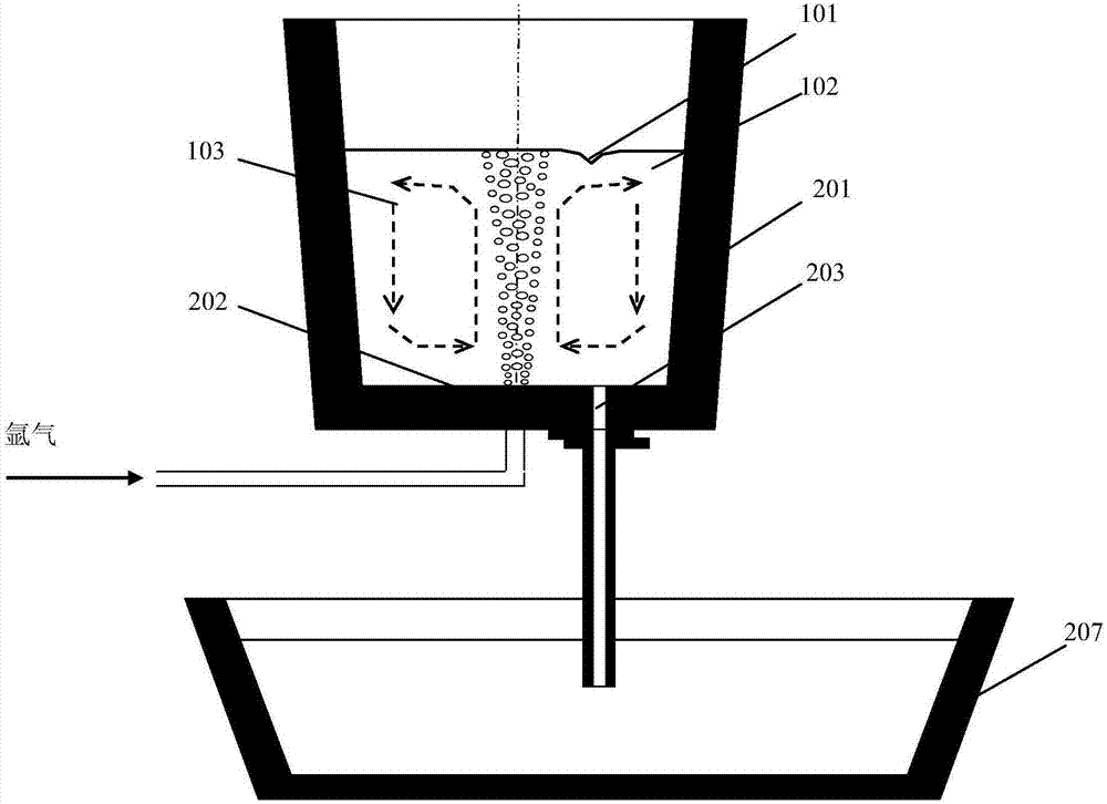
[0005] Aiming at the deficiencies of various anti-swirl methods in the existing ladle tapping process, the present invention provides a method for blowing argon to prevent the vortex slag entrainment in the ladle tapping process. Blow air at a small flow rate throughout the whole process, thereby disturbing the flow field distribution when the vortex is formed, and completely eliminating the formation of the vortex and the occurrence of vortex slag entrainment

Method used


Image

  • Method of preventing vortex slag entrapment through argon blowing in steel ladle tapping process
  • Method of preventing vortex slag entrapment through argon blowing in steel ladle tapping process
  • Method of preventing vortex slag entrapment through argon blowing in steel ladle tapping process

Examples


Embodiment 1

[0024] Using the water model experimental device, in the process of tapping through image 3 No. 1 gas blowing hole 202 in the middle respectively blows gas with a flow rate of 0-1.3 L / min. When the blowing flow rate is 0L / min, that is, the critical height of the vortex is as high as 9.4cm when there is no blowing during the tapping process. After the gas is introduced, the critical height of the vortex decreases significantly with the increase of the blowing flow rate. When the blowing air flow rate is 0.04L / min, the critical height of the vortex drops to 5.5cm; when the air blowing flow rate is 1.3L / min, the critical height of the vortex drops to a minimum of 1.8cm. Therefore, it can be calculated that the final liquid yield obtained in the water model experiment carried out according to the present invention can be increased by about 13%.

[0025] According to the above experimental results, according to the conversion formula Q between the simulated gas and the actual blo...

Embodiment 2

[0028] Using the described water model experimental device, in the process of tapping, through image 3 Middle No. 1-No. 8 blowing hole 202 is blown into the gas that flow rate is 0.06L / min, obtains as follows Figure 5 the experimental results. Depend on Figure 5 It can be seen that the critical height of the vortex is very high when there is no air blowing in the tapping process, but when blowing air through No. 1-8 air blowing holes 202, the critical height of the vortex is significantly reduced. Therefore, in practice, the ladle 201 can be used to refine The air blowing hole 202 used can obtain an obvious swirl suppression effect. In contrast, the effect of suppressing the vortex is the best when blowing air through the No. 7 blowing hole 202 , that is, the position of the blowing hole 202 is close to the center of the ladle 201 , and the effect of suppressing the vortex is relatively good. At the same time, blow air at the best blowing hole 202 position. When the blow...

Embodiment 3

[0031] Using the numerical simulation method, simulated in the tapping process through the Image 6 The specific setting of the slag entrainment after blowing with different air blowing holes in is as follows: without blowing, the blowing flow rate is 0L / min; for single hole blowing, the position of the blowing hole is No. 1 blowing hole, and the blowing flow rate is 100L / min , double-hole blowing, the blowing holes are located at No. 1 and No. 2 blowing holes, and the total blowing flow rate is 100L / min (the single-hole flow rate is 50L / min); double-hole blowing, the positions of the blowing holes are No. 1 and No. 3 , the total blowing flow rate is 100L / min (single hole flow rate is 50L / min). The distance between each blowing hole and the nozzle is R / 4 (R is the radius of the bottom of the ladle). Figure 7 It can be found from the simulation results that whether it is single-hole air blowing or double-hole air blowing, the critical height of the vortex can be significantly...


PUM


Abstract

The invention relates to a method of preventing a vortex slag entrapment phenomenon through argon bottom-blowing in a steel ladle tapping process, and belongs to the technical field of metallurgy. In a steel ladle pouring process, small flow rate blowing is carried out through a blowing hole in the bottom of a steel ladle, thereby disturbing distribution of a flow field formed by a vortex in the tapping process, and thoroughly inhibiting formation of the vortex and occurrence of the vortex slag entrapment phenomenon. The method has the following advantages: without changing the structure of the steel ladle, the vortex slag entrapment phenomenon can be eliminated effectively, the cleanness of molten steel can be improved and a metal yield can be raised; the blowing hole used during refining can be adopted, no blowing hole is necessarily formed near a nozzle, multiple blowing holes may be adopted selectively, and neither the one blowing hole nor the multiple blowing holes may cause large temperature drop of molten steel flowing into a tundish; and small flow rate argon blowing is carried out in the tapping overall process, so that a certain function is exerted in further facilitating an entrapped substance to float upwards and facilitating molten steel temperature uniformization, and no molten steel exposure is caused.

Description

technical field [0001] The invention belongs to the technical field of metallurgy, and in particular relates to a method for blowing argon to prevent vortex slag entrainment during the tapping process of a ladle. Background technique [0002] With the continuous development of various industries such as aerospace, transportation, petroleum and automobiles, the requirements for steel performance in various fields are constantly increasing. Therefore, how to reduce inclusions in steel, improve the cleanliness of steel, and then improve the quality of steel to obtain high performance High-quality steel is one of the issues that iron and steel companies are widely concerned about. The continuous casting process is an important link in the production of clean steel, which has a great impact on the cleanliness of the steel. Among them, the vortex slag phenomenon generated during the ladle tapping process seriously affects the cleanliness of the molten steel, pollutes the molten st...

Claims


Application Information

Patent Timeline
Patent Type & Authority Applications(China)
IPC IPC(8): C21C7/072B22D41/58
CPCC21C7/072B22D41/58
Inventor 王强李宏侠王连钰蒋佳伟赫冀成
Owner NORTHEASTERN UNIV
Learn More