
Non-synchronous drive edging cutting machine

A cutting machine, asynchronous technology, applied in the direction of grinding frame, grinding machine parts, machine tool suitable for grinding workpiece edge, etc., can solve the problems of high product cost, waste of energy, etc., to achieve convenient operation, prevent Burn-out, easy-to-control effects

Inactive Publication Date: 2017-07-21
GUANGDONG SINID TECH
View PDF5 Cites 9 Cited by
  • Summary
  • Abstract
  • Description
  • Claims
  • Application Information

AI Technical Summary

Problems solved by technology

For example, the 650 type 48+4 edging machine needs 48 edging and cutting devices. If the disclosed automatic feed grinding device is adopted, 48 feed motors are required to meet the requirements, so the product cost is high
[0004] In addition, when using the above-mentioned 650-type 48+4 edge grinder to grind ceramic tiles, the grinding heads on all stations need to be fed or retracted synchronously, and when some of the stations do not cut ceramic tiles, these The grinding head of the station is idling without cutting, which is equivalent to a waste of energy, so it is necessary to improve the defects in the above technology

Method used


Image

  • Non-synchronous drive edging cutting machine
  • Non-synchronous drive edging cutting machine
  • Non-synchronous drive edging cutting machine

Examples


Embodiment Construction

[0044] The technical solutions of the present invention will be further described below in conjunction with the accompanying drawings and through specific implementation methods.

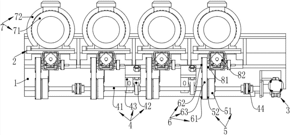
[0045] Such as figure 1 with figure 2 Shown, a kind of non-synchronous drive edging cutting machine comprises beam 1, processing transmission device 2, main power device 3, power transmission device 4, clutch 5, pulley transmission device 6 and processing grinding device 7; The transmission device 2, the main power device 3, the power transmission device 4, the clutch 5, the pulley transmission device 6 and the processing and grinding device 7 are all installed on the beam 1;

[0046] The main power device 3 is used to drive the processing transmission device 2;

[0047] The processing transmission device 2 drives the pulley transmission device 6 to rotate through the clutch 5;

[0048] The pulley transmission device 6 is used to drive the processing transmission device 2 to move;

[0049] The ...


PUM


Abstract

The invention relates to the technical field of peripheral processing equipment for daily-use architectural ceramics. A non-synchronous drive edging and cutting machine, including a beam, a processing transmission device, a main power device, a power transmission device, a clutch, a pulley transmission device, and a processing and grinding device; the processing transmission device, the main power device, and the power transmission device , clutch, pulley transmission and processing and grinding device are all installed on the beam; the main power device is used to drive the processing transmission; the processing transmission drives the pulley transmission through the clutch to rotate; the pulley The transmission device is used to drive the processing transmission device to move; the processing transmission device is used to drive the processing and grinding device to move; the processing and grinding device is used to grind ceramic tiles; the processing transmission device, processing and grinding device, clutch and There are multiple pulley transmissions corresponding to each other, and each clutch independently controls the rotation of each pulley transmission.

Description

technical field [0001] The invention relates to the technical field of peripheral processing equipment for daily-use architectural ceramics, in particular to an asynchronously driven edge grinding and cutting machine. Background technique [0002] Existing ceramic bricks are fired and formed, and better brick edge quality is obtained after grinding, and this process is obtained by manually adjusting the feed rate of the edging wheel from time to time to ensure that the bricks meet the size inspection standard , The manual labor intensity is high, the technical level of the operator directly affects the product quality, and the dependence on personnel is large, which makes the labor cost of the enterprise high. In response to this demand, an automatic feeding device is urgently needed to solve the current predicament. [0003] Because the prior art requires multiple groups of cutting grinding heads to simultaneously feed and grind ceramic tiles or withdraw from grinding duri...

Claims


Application Information

Patent Timeline
Patent Type & Authority Applications(China)
IPC IPC(8): B24B9/06B24B27/00B24B41/02B24B55/00B24B47/12
CPCB24B9/06B24B27/0023B24B27/0076B24B41/02B24B47/12B24B55/00
Inventor 杨扬叶金伟姚明杰
Owner GUANGDONG SINID TECH
Learn More