Energy-saving iron smelting furnace

An iron melting furnace and furnace body technology, which is applied in the field of iron and steel smelting, can solve the problems of high chimney, impact on workers' health, long payback period, etc., and achieve the effect of reducing working time, benefiting health and reducing expenses.

Inactive Publication Date: 2017-07-18
MAANSHAN NIUZE TECH SERVICE
View PDF0 Cites 0 Cited by
  • Summary
  • Abstract
  • Description
  • Claims
  • Application Information

AI Technical Summary

Problems solved by technology

[0002] At present, the equipment for melting molten iron in the foundry industry is mainly cold weathered iron furnace and hot weathered iron furnace. The cold weathered iron furnace uses a blower to blow cold air directly into the furnace to promote the combustion of coke and the melting of iron. It is not conducive to the increase of the temperature in the furnace, and the consumption of coke is large. The hot weathering iron furnace mainly uses iron slag and mechanical iron filings as smelting raw materials. Its chimney is high, the investment is large, and the recovery period is long. When the iron block contains impurities such as sulfur, hydrogen sulfide and other gases will be produced during melting, and these gases containing hydrogen sulfide are directly discharged into the air, and the gas containing hydrogen sulfide is full of pungent odor, which is directly discharged into the workshop. It has a great impact on the health of workers. Workers working in this environment are prone to occupational diseases. Traditional melting furnaces cannot observe the melting of iron in the furnace. When pouring molten iron in the furnace, it is also a manual operation, and accidents are inevitable.

Method used


Image

  • Energy-saving iron smelting furnace
  • Energy-saving iron smelting furnace

Examples


Embodiment Construction

[0011] The following will clearly and completely describe the technical solutions in the embodiments of the present invention with reference to the accompanying drawings in the embodiments of the present invention. Obviously, the described embodiments are only some of the embodiments of the present invention, not all of them. Based on the embodiments of the present invention, all other embodiments obtained by persons of ordinary skill in the art without making creative efforts belong to the protection scope of the present invention.

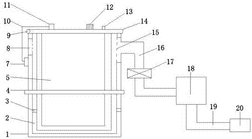
[0012] see Figure 1-2 , the present invention provides a technical solution: an energy-saving iron smelting furnace, including a furnace body 5, an outer frame 1, a furnace cover 14 and a gas treatment device, the inner side of the outer frame 1 is provided with a groove frame 2 for accommodating the furnace body 5, the groove frame In order to be able to fix and accommodate the furnace body, the shape of the groove frame matches the furnace bod...


PUM


Abstract

The invention discloses an energy-saving iron smelting furnace, which mainly includes a furnace body, an outer frame, a furnace cover and a gas processing device. A groove frame for accommodating the furnace body is arranged on the inner side of the outer frame, and a rotating shaft is installed on the corresponding two sides of the outer frame. , the furnace body is connected to the outer frame through a rotating shaft, an opening is provided on one side of the slot frame, a baffle is provided on the opening surface, the baffle is welded on the outer frame, and a heat dissipation Hole and hollow body, the heat dissipation holes connect the slot frame with the hollow body, the top of the outer frame is connected to the furnace cover through a circular hinge, a gas treatment device is provided on one side of the outer frame, and a gas treatment device is provided on one side of the furnace cover. A camera, the camera is connected to the display through wires, and the other side of the furnace cover is also provided with a temperature sensor and an alarm lamp. The invention has simple structure and reasonable design, and the hydrogen sulfide gas generated during iron melting is discharged after being treated by a gas treatment device, thereby reducing waste gas discharge.

Description

technical field [0001] The invention relates to the technical field of iron and steel smelting, in particular to an iron melting furnace. Background technique [0002] At present, the equipment for melting molten iron in the foundry industry is mainly cold weathered iron furnace and hot weathered iron furnace. The cold weathered iron furnace uses a blower to blow cold air directly into the furnace to promote the combustion of coke and the melting of iron. It is not conducive to the increase of the temperature in the furnace, and the consumption of coke is large. The hot weathering iron furnace mainly uses iron slag and mechanical iron filings as smelting raw materials. Its chimney is high, the investment is large, and the recovery period is long. When the iron block contains impurities such as sulfur, hydrogen sulfide and other gases will be produced during melting, and these gases containing hydrogen sulfide are directly discharged into the air, and the gas containing hydro...

Claims


Application Information

Patent Timeline
IPC IPC(8): F27B14/00F27B14/08
CPCF27B14/00F27B14/08F27B2014/002
Inventor 施享张伟
Owner MAANSHAN NIUZE TECH SERVICE
Why Eureka
Try Eureka