A High Speed ​​Clock Receiver Circuit with Programmable Adjustable Common Mode Level

A high-speed clock and receiving circuit technology, applied in electrical components, pulse technology, pulse processing and other directions, can solve the problem of not transmitting common mode level, etc., to achieve the effect of improving flexibility, increasing complexity, and increasing ineffective power consumption

Active Publication Date: 2020-07-03
BEIJING MXTRONICS CORP +1
View PDF4 Cites 0 Cited by
  • Summary
  • Abstract
  • Description
  • Claims
  • Application Information

AI Technical Summary

Problems solved by technology

However, due to the influence of non-ideal factors such as process matching, power supply jitter and circuit noise, the common mode level is not the best transmission common mode level, and it needs to be adjusted in the specific application environment to realize the common mode level. Optimum performance for high-speed clock receiving circuits

Method used


Image

  • A High Speed ​​Clock Receiver Circuit with Programmable Adjustable Common Mode Level
  • A High Speed ​​Clock Receiver Circuit with Programmable Adjustable Common Mode Level
  • A High Speed ​​Clock Receiver Circuit with Programmable Adjustable Common Mode Level

Examples


Embodiment Construction

[0036] Below in conjunction with accompanying drawing and specific embodiment the present invention is described in further detail:

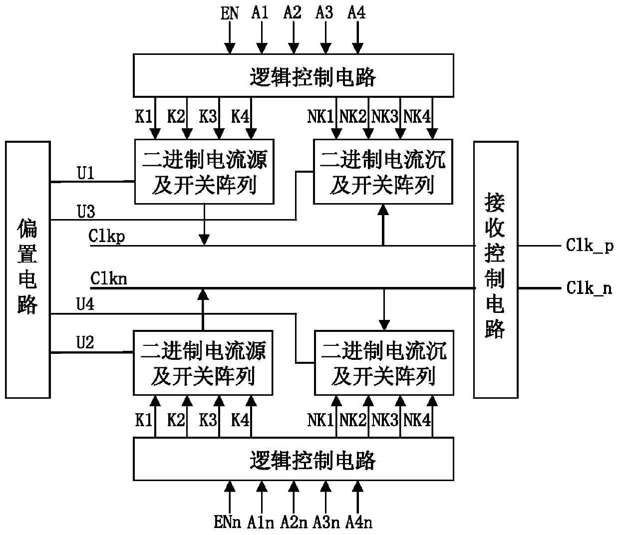
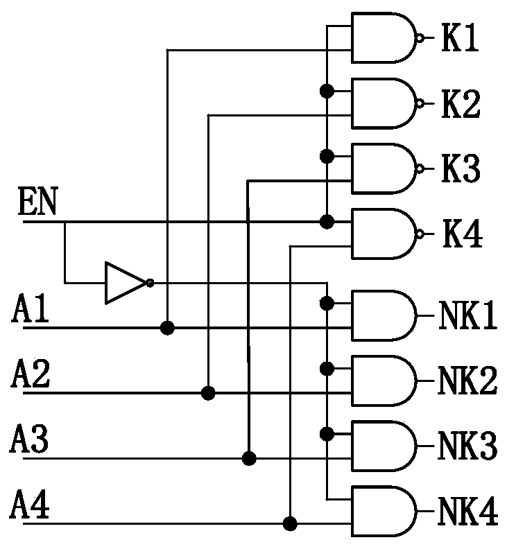
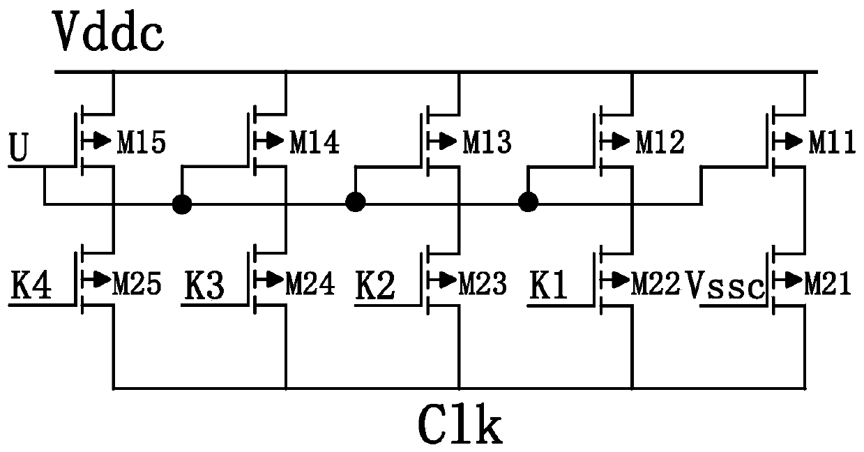
[0037] Such as figure 1 As shown, a high-speed clock receiving circuit with programmable adjustment of common mode level includes bias circuit, logic control circuit, binary current source and switch array, binary current sink and switch array and receiving control circuit. The bias circuit provides bias to the binary current source and switch array, the binary current sink and the switch array; the logic control circuit decodes the input control code word into the switch control signal of the binary current source and the switch array, the binary current sink and the switch array ;The binary current source and switch array and the binary current sink and the switch array are respectively connected to the clock input terminal to supplement and extract the current to realize the adjustment of the common mode level of the clock signal; the input c...


PUM


Abstract

The invention relates to a high-speed clock receiving circuit capable of programmably adjusting common mode levels. The circuit comprises a bias circuit, logic control circuits, binary current source and switch arrays, binary current sink and switch arrays, and a receiving control circuit. After the bias circuit is electrified, voltage bias is supplied to current source and current sink arrays, thereby controlling initial currents and initial levels. The logic control circuits decode input control codons into switch control signals of the current source and current sink switch arrays. The binary current source and switch arrays and binary current sink and switch arrays are connected with clock input ends and are used for supplementing and extracting currents, thereby adjusting clock signal common mode levels. The receiving control circuit is used for controlling transmission of the common mode levels and input of the differential clocks. According to the circuit, the high-speed differential clock common mode levels are adjusted flexibly between 0.8-1V through input codons, influences of the common mode levels on the input of high-speed differential clock signals can be eliminated, and the high-performance clock receiving circuit is realized.

Description

technical field [0001] The invention relates to a high-speed clock receiving circuit with programmable common-mode level adjustment, and belongs to the technical field of high-speed clock receiving. Background technique [0002] High-speed clock signals are usually used in military equipment such as wireless communication equipment and radar, and high-performance high-speed clock receiving circuits are crucial. The common-mode level of the differential clock signal directly affects the effect of receiving the clock by the high-speed clock receiving circuit. If the common mode level is too low, the low level of the differential clock signal will be distorted, or even cannot be input; if the common mode level is too high, the high level of the differential clock signal will be distorted, or even cannot be input. Due to the influence of non-ideal factors such as noise and mismatch during transmission, the common-mode level of the high-speed differential clock generally has a l...

Claims


Application Information

Patent Timeline
Patent Type & Authority Patents(China)
IPC IPC(8): H03K5/131H03K5/135
CPCH03K5/131H03K5/135
Inventor 张雷彭新芒王宗民
Owner BEIJING MXTRONICS CORP
Why Eureka
Try Eureka