
Pan-tilt, and control method and apparatus for pan-tilt motor

A control method and technology of a control device, applied in the field of pan/tilt, can solve the problems of complex control scheme, complex overall design, motor heating, etc., and achieve the effects of simplifying the structure design of the pan/tilt, reducing mutual influence, and reducing the total volume

Inactive Publication Date: 2017-07-14
NINEBOT (BEIJING) TECH CO LTD
View PDF2 Cites 25 Cited by
  • Summary
  • Abstract
  • Description
  • Claims
  • Application Information

AI Technical Summary

Problems solved by technology

When a brushless motor is used, a control method of the pan-tilt motor is called motor closed-loop vector control. This control method needs to know the rotation angle of the motor rotor relative to the stator in order to control the correct commutation of the motor magnetic field and ensure the stable torque output of the motor. , this approach is also called motor closed-loop vector control; in addition, this control method generally uses a rotation angle detection sensor to detect the rotation angle of the motor rotor relative to the stator. Commonly used rotation angle detection sensors include grating encoders, magnetic encoders, linear Hall or potentiometer However, because each motor has a rotation angle detection sensor, the control scheme is more complicated, and the pan / tilt structure needs to cooperate with the rotation angle detection sensor and the motor drive board, so the overall design is complicated and the cost is high
Another control method of the pan / tilt motor is to directly adopt open-loop control on the motor. When the pan / tilt is disturbed by a continuous external force, the torque of the motor will fluctuate greatly, and even reverse torque will appear periodically. The phenomenon of the motor is also called the step loss of the motor; moreover, after the external disturbance disappears and the gimbal returns to the target position, the motor still consumes a large amount of current and the efficiency is low. Slow, the use effect of the gimbal is not ideal, but the control and structure of the gimbal are relatively simple and the cost is low

Method used


Image

  • Pan-tilt, and control method and apparatus for pan-tilt motor
  • Pan-tilt, and control method and apparatus for pan-tilt motor
  • Pan-tilt, and control method and apparatus for pan-tilt motor

Examples


Embodiment 1

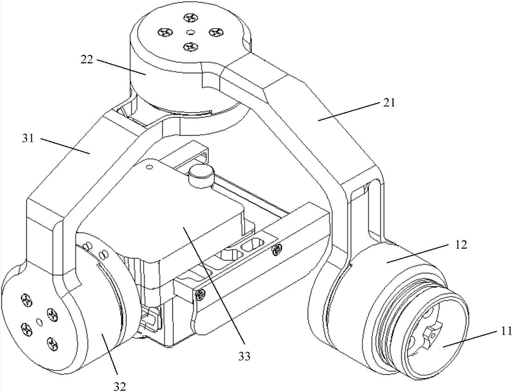
[0047] Embodiment 1 of the present invention provides a control method for a pan-tilt motor. The method is used to control the pan-tilt motor. The pan-tilt is a multi-axis pan-tilt, and the multi-axis is at least two axes, such as: two Axis pan / tilt, three-axis pan / tilt, etc.; each axis corresponds to a shaft motor, for example: a two-axis pan / tilt can include two shaft motors, and each shaft motor rotates around an axis (such as around the x-axis, y-axis rotation), the three-axis gimbal can include three shaft motors, and each shaft motor rotates around an axis (such as rotating around the x-axis, y-axis, and z-axis respectively); each shaft motor is composed of a corresponding rigid body member to host, for example: see figure 1 In the shown three-axis cloud platform structure, the first rigid body member 11 is used to carry the first rotating shaft motor 12, and the first rigid body member 11 is also used as a rigid body member supporting the entire cloud platform, and the ...

Embodiment 2

[0066] like image 3 As shown, the second embodiment is a three-axis cloud platform, the first rigid body member 11 is used to carry the first rotating shaft motor 12, and the first rigid body member 11 is also used as a rigid body member supporting the entire cloud platform, the first rigid body member 11 It can be fixed on the support seat, such as on the base of the drone, or on the body or head base of the ground mobile robot, or on the handle base of the gimbal of the hand-held stabilizer, etc. Two rigid body members 21 connect the first rotating shaft motor 12 and the second rotating shaft motor 22, the second rigid body member 21 is used to carry the second rotating shaft motor 22, the third rigid body member 31 connects the second rotating shaft motor 22 and the third rotating shaft motor 32, and the second rigid body member 21 connects the second rotating shaft motor 22 and the third rotating shaft motor 32. The three shaft motors 32 are connected to the carrier platf...

Embodiment 3

[0070] like Figure 4 As shown, embodiment three is a three-axis cloud platform, the first rigid body member 11 is used to carry the first rotating shaft motor 12, and the first rigid body member 11 is also used as a rigid body member supporting the entire cloud platform, the first rigid body member 11 It can be fixed on the support seat, such as on the base of the drone, or on the body or head base of the ground mobile robot, or on the handle base of the gimbal of the hand-held stabilizer, etc. Two rigid body members 21 connect the first rotating shaft motor 12 and the second rotating shaft motor 22, the second rigid body member 21 is used to carry the second rotating shaft motor 22, the third rigid body member 31 connects the second rotating shaft motor 22 and the third rotating shaft motor 32, and the second rigid body member 21 connects the second rotating shaft motor 22 and the third rotating shaft motor 32. The three shaft motors 32 are connected to the carrier platform ...


PUM


Abstract

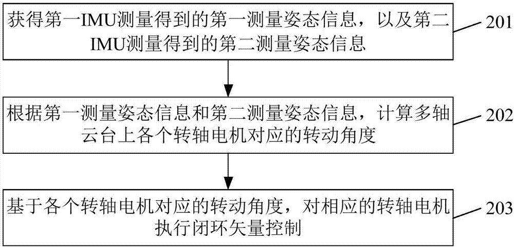
The invention discloses a method for controlling a pan-tilt motor. The pan-tilt is a multi-axis pan-tilt, and the multi-axis is at least two axes. The rigid body member is carried, the carrier platform of the platform is provided with a first inertial measurement unit (IMU), and at least one rigid body member used to carry the shaft motor is provided with a second IMU, the method Including: obtaining the first measurement attitude information obtained by the first IMU measurement, and the second measurement attitude information obtained by the second IMU measurement; according to the first measurement attitude information and the second measurement attitude information, calculating the The rotation angles corresponding to the respective rotating shaft motors on the multi-axis pan / tilt; based on the corresponding rotating angles of the respective rotating shaft motors, closed-loop vector control is performed on the corresponding rotating shaft motors. The invention also discloses a control device of the pan-tilt motor and the pan-tilt.

Description

technical field [0001] The present invention relates to the technical field of pan / tilts, such as airborne aerial photography pan / tilts, vehicle-mounted pan / tilts, and hand-held stabilizer pan / tilts, etc., and particularly relates to a pan / tilt and a control method and device for a pan / tilt motor. Background technique [0002] General drone aerial photography gimbals, vehicle gimbals and electronic gyroscope handheld stabilizer gimbals are all driven by servo motors, which can be brushed or brushless. When a brushless motor is used, a control method of the pan-tilt motor is called motor closed-loop vector control. This control method needs to know the rotation angle of the motor rotor relative to the stator in order to control the correct commutation of the motor magnetic field and ensure the stable torque output of the motor. , this approach is also called motor closed-loop vector control; in addition, this control method generally uses a rotation angle detection sensor to ...

Claims


Application Information

Patent Timeline
IPC IPC(8): H02P5/46H02P5/52H02P21/14
CPCH02P5/46H02P5/52H02P21/14
Inventor 袁玉斌陈中元
Owner NINEBOT (BEIJING) TECH CO LTD
Learn More