Pull type clutch assembly test tool

A technology for testing tooling and clutches, which is applied in the field of clutches, can solve the problems of lack of test tooling for pull-type clutch cover assemblies and insufficient testing methods, and achieve the effects of increasing pressure, improving detection results, and reducing tooling costs

Pending Publication Date: 2017-07-14
WUHU DAJIE CLUTCH
View PDF4 Cites 2 Cited by
  • Summary
  • Abstract
  • Description
  • Claims
  • Application Information

AI Technical Summary

Problems solved by technology

[0003] The purpose of the present invention is to provide a pull-type clutch assembly test tool to solve the technical problem that there is no pull-type clutch cover assembly test tool and testing means in the prior art.

Method used


Image

  • Pull type clutch assembly test tool
  • Pull type clutch assembly test tool
  • Pull type clutch assembly test tool

Examples


Embodiment 1

[0031] Such as Figure 1-6 As shown, a pull clutch assembly test fixture, including:

[0032] Base 5;

[0033] The clutch assembly fixed bracket, the clutch assembly fixed bracket is arranged on the base, including the lower fixed bracket 4 and the limit piece 3 arranged above the lower fixed bracket, the lower fixed bracket 4 is provided with four connecting rods 41 and six The fixed end 42, the lower fixed bracket 4 is connected with the limiter 3 through the connecting rod 41, and the center of the limiter 3 is provided with a detection through hole 31;

[0034] The detection part, when performing the clutch assembly test, the clutch assembly is fixed between the lower fixing bracket and the limiter through the fixed end, the detection part is placed on the clutch assembly, and is located in the detection through hole, and the limiter The center point of is on the axis of the clutch assembly.

[0035] When testing the clutch assembly, install the test tool on the testing...

Embodiment 2

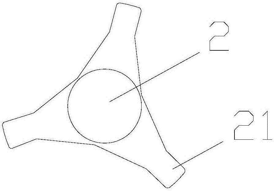
[0042] Compared with Embodiment 1, the detection part in this embodiment is different from that in Embodiment 1. The detection part is used to detect the big end of the diaphragm spring, and other parts are the same as in Embodiment 1. Such as Figure 7 , 8 As shown, the detection part is disc-shaped, and three protrusions 21 are uniformly arranged on the outer periphery of the detection part 2 along its radial direction. The detection part is used to detect the strength of the large end of the diaphragm spring of the clutch assembly. For a pull clutch, during the period of time when the clutch pedal is not stepped on during the driving phase of the vehicle, the large end of the diaphragm spring presses the pressure plate to ensure that the driven plate and The flywheels are close together, so the large end of the diaphragm spring is under pressure for a long time, so the strength of the large end of the diaphragm spring needs to meet the requirements. During the test, the th...


PUM


Abstract

The invention discloses a pull type clutch assembly test tool comprising a base, a clutch assembly fixing support and a detection part. The clutch assembly fixing support is arranged on the base. A lower fixing support is connected with a limiting member through a connecting rod. The center of the limiting member is provided with a detection through hole. The clutch assembly is fixed between the lower fixing support and the limiting member through a fixing end. The detection part is arranged on the clutch assembly and positioned in the detection through hole. The test tool is installed on detection equipment in detection, the lower fixing support is arranged on the base, the clutch assembly is fixed on the lower fixing support by the installing hole through the edge of the clutch cover of the fixing end, then the limiting member is arranged on the fixing support, the detection part is arranged on the clutch assembly and the detection part is positioned in the detection through hole so that force bearing of the clutch assembly is enabled to be uniform in testing, the test result is accurate, and finally the pressing column of the detection equipment is abutted against the center of the detection part to perform pressing detection.

Description

technical field [0001] The invention belongs to the technical field of clutches, and in particular relates to a pull-type clutch assembly testing tool. Background technique [0002] The difference between a pull clutch and a push clutch is that the working direction and shape of the diaphragm spring are different when it is separated: when the push clutch is separated, the separation finger of the diaphragm spring bears the thrust, and the installation direction of the diaphragm spring in the pull clutch Contrary to the traditional push-type structure, the support point is moved to the vicinity of the large end of the diaphragm spring. With this structure, when testing the clutch cover assembly, the test tooling for the general push-type cover assembly cannot meet the test requirements. Features. Contents of the invention [0003] The purpose of the present invention is to provide a pull clutch assembly testing tool to solve the technical problem that there is no pull clu...

Claims


Application Information

Patent Timeline
IPC IPC(8): G01M13/02G01N3/08
CPCG01M13/022G01N3/08
Inventor 张浩胡恒煊毕承琪吴强
Owner WUHU DAJIE CLUTCH
Why Eureka
Try Eureka