
A kind of 3D printer that recycles the plastic used for 3D printing and printing method thereof

A 3D printer, 3D printing technology, applied in the direction of processing and recycling, 3D object support structure, manufacturing tools, etc., can solve the problems of unrealistic equipment, inconvenient use, uneconomical, etc. Effect

Active Publication Date: 2020-05-29
MOXIN (HUZHOU) TECH CO LTD
View PDF1 Cites 0 Cited by
  • Summary
  • Abstract
  • Description
  • Claims
  • Application Information

AI Technical Summary

Problems solved by technology

Most of these devices are for industrial purposes, bulky and inconvenient to use
It is not economical for ordinary makers or home users and small studios, and it is not practical to equip these devices

Method used


Image

  • A kind of 3D printer that recycles the plastic used for 3D printing and printing method thereof
  • A kind of 3D printer that recycles the plastic used for 3D printing and printing method thereof
  • A kind of 3D printer that recycles the plastic used for 3D printing and printing method thereof

Examples


Embodiment 1

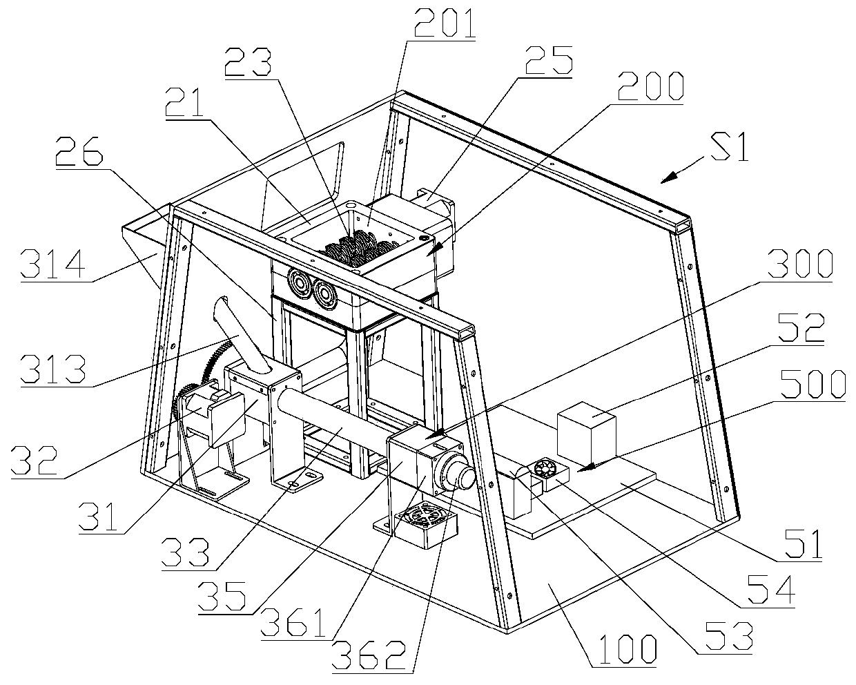
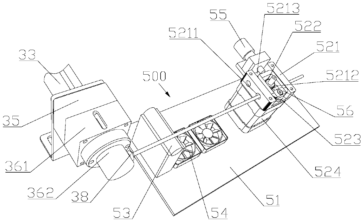
[0049] First, combine Figure 2 to Figure 4 See cooling traction assembly 500.

[0050] The cooling traction assembly 500 includes a support base plate 51 and a conveyor 52 arranged on the support base plate 51. The support base plate 51 is detachably connected to the main frame 100, so that the modular installation of the cooling traction assembly 500 can be realized. The conveyor 52 has a wire passage, The extrusion nozzle 38 is located on the same straight line as the wire passage.

[0051] Conveyor 52 comprises conveying seat 521, conveying driving wheel 522, conveying driven wheel 523 and conveying motor 524, the output shaft of conveying motor 524 passes conveying seat 521, and conveying driving wheel 522 can be directly installed on the output shaft of conveying motor 524, The conveying motor 524 drives the conveying driving wheel 522, and the conveying driven wheel 523 is rotatably connected to the conveying seat 521. A conveying gap is formed between the conveying dr...

Embodiment 2

[0071] In order to improve the heat insulation effect, this embodiment adds a cooling element on the basis of Embodiment 1, specifically as Figure 11 and Figure 12 As shown, a cooling element 37 is provided between the heat insulating element 35 and the downstream end of the feeding cylinder 33, the cooling element 37 is provided with a cooling pipe 371, and the cooling pipe 371 communicates with a water pump 372 and a water tank 373 to form a cooling cycle, and the heat insulating element 35 passes The cooling element 37 is connected with the feeding cylinder, and the cooling element 37 is provided with a cooling passage 370, and the downstream end of the feeding cylinder 33, the cooling passage 370, and the heat-insulating passage 351 communicate with the hot melt chamber in sequence. Because the cooling element 37 adopts the mode of circulating cooling, the cooling effect is relatively good, and the melting of the plastic in the feeding cylinder 33 can be avoided better. ...

Embodiment 3

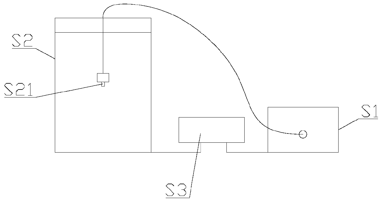
[0075] The present invention also provides a printing method of the 3D printer in the above embodiment, such as figure 1 As shown, the printing device includes a printing nozzle S21, and the specific printing method includes the following steps:

[0076] Step 1, parameter preparation, input the model data file into the controller, and the controller obtains the theoretical printing speed of the printing nozzle S21 in each unit time, and the theoretical extrusion speed V of the melt extrusion component in each unit time 0 and with V 0 Real-time corresponding theoretical wire diameter D 0 ;

[0077] Step 2, put the recycled plastic into the crushed material component, and the crushed material component crushes the recycled plastic into plastic granules and transports them to the melt extrusion component;

[0078] Step 3, the printing device is preheated;

[0079] Step 4, the melting extrusion component melts the plastic particles through the melting cavity and extrudes the p...


PUM


Abstract

The invention discloses a 3D printing machine for recycling 3D printing plastic and belongs to the field of 3D printing. The 3D printing machine solves the problem that in the prior art, recycled 3D printing plastic cannot be directly printed. According to the technical scheme for solving the problem, the 3D printing machine mainly comprises a recycling device and a printing device. The recycling device comprises a main rack, a material smashing assembly and a melting extrusion assembly, wherein the material smashing assembly and the melting extrusion assembly are located on the main rack. The material smashing assembly is used for smashing recycled plastic into plastic particles and conveying the plastic particles into the melting extrusion assembly. The melting extrusion assembly is used for melting the plastic particles and extruding the plastic particles to form a plastic line. The recycling device further comprises a cooling traction assembly. The cooling traction assembly is used for cooling the plastic line and conveying the plastic line to the printing device. The melting extrusion assembly comprises a melting cavity and an extrusion nozzle. The cooling traction assembly is located on the transverse side of the melting cavity, and the extrusion nozzle faces the cooling traction assembly. The 3D printing machine is mainly used for improving the printing quality of direct printing of the recycled 3D printing plastic. The invention further provides a printing method of the above 3D printing machine.

Description

technical field [0001] The invention relates to a 3D printer, in particular to a 3D printer which recycles plastics for 3D printing and a printing method thereof. Background technique [0002] As a rapid prototyping device, 3D printers are increasingly being used in production and life. Some schools, makers and small studios are also equipped with small 3D printers. Most of the existing small 3D printers are fusion deposition models, using plastic or materials with similar properties as printing consumables. During the printing process, discarded and useless 3D printed parts are often generated due to various reasons such as parameter errors or interruptions in the middle. Most of the existing disposal methods for such printouts are directly discarded. However, direct discarding of the waste prints produced will not only pollute the environment but also be uneconomical. [0003] However, most of the existing plastic recycling methods for 3D printing use special drying an...

Claims


Application Information

Patent Timeline
Patent Type & Authority Patents(China)
IPC IPC(8): B29C64/118B29C64/357B29C64/314B29C64/321B29C64/393B33Y30/00B33Y40/00B33Y40/10B33Y50/02
CPCB33Y30/00B33Y40/00
Inventor 陈天润
Owner MOXIN (HUZHOU) TECH CO LTD
Learn More