
Transmission line monitoring method and transmission line monitoring device

A transmission line and abnormal location technology, applied in the direction of circuit devices, electrical components, fault locations, etc., can solve problems such as the lack of a better monitoring solution for transmission lines, and the inability of transmission lines to respond to grid faults, etc.

Inactive Publication Date: 2017-06-20
国网山东省电力公司临邑县供电公司 +1
View PDF5 Cites 37 Cited by
  • Summary
  • Abstract
  • Description
  • Claims
  • Application Information

AI Technical Summary

Problems solved by technology

[0005] In view of this, the purpose of the present invention is to provide a transmission line monitoring method and device to alleviate the problem in the prior art that there is no better monitoring solution for transmission lines and cannot respond to grid failures in time when the transmission line is abnormal

Method used


Image

  • Transmission line monitoring method and transmission line monitoring device
  • Transmission line monitoring method and transmission line monitoring device
  • Transmission line monitoring method and transmission line monitoring device

Examples


Embodiment 1

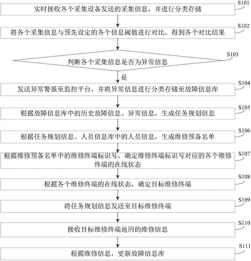
[0092] figure 1 It shows a schematic flowchart of a method for monitoring a transmission line provided by an embodiment of the present invention. Such as figure 1 As shown, the transmission line monitoring method includes:

[0093] Step S101: Receive collection information sent by each collection device in real time, and perform classified storage.

[0094] Among them, each collection equipment includes positioning equipment, camera equipment, infrared thermal imaging cameras, visibility sensors, temperature and humidity sensors, wind speed sensors, yaw distance sensors, inclination sensors, inclination acceleration sensors, ultrasonic rangefinders, micro-meteorological monitoring equipment and infrared One or more of the sensors, the above-mentioned camera equipment is installed on the pan / tilt, and other acquisition equipment can be directly installed in the tower, wire or substation. Specifically, after receiving the collection information of each collection device, it is class...

Embodiment 2

[0142] Figure 4 It shows a schematic structural diagram of a power transmission line monitoring device provided by an embodiment of the present invention. Such as Figure 4 As shown, the transmission line monitoring device includes:

[0143] The information receiving module 510 is used to receive the collected information sent by each collection device in real time, and perform classified storage;

[0144] The information comparison module 511 is used to compare each collected information with each preset information threshold to obtain each comparison result;

[0145] The abnormality judgment module 512 is used to judge whether each collected information is abnormal information according to the comparison result;

[0146] The alarm sending module 513 is used to send an abnormal alarm to the monitoring platform when the collected information is abnormal information, and classify and store the abnormal information in the fault information database;

[0147] The planning generation modu...


PUM


Abstract

The invention provides a transmission line monitoring method and a transmission line monitoring device. The transmission line monitoring method comprises the following steps: comparing acquisition information sent by multiple pieces of acquisition equipment with preset information thresholds respectively to get comparison results; if judging that the acquisition information is abnormal information according to the comparison results, sending an abnormality alarm to a monitoring platform; generating task planning information and a maintenance preparation list according to the historical fault information in a fault information base, the abnormal information, and the personnel information in a personnel information base; determining whether each of maintenance terminals corresponding to maintenance terminal identification numbers in the maintenance preparation list is online; determining a target maintenance terminal; sending the task planning information to the target maintenance terminal; receiving maintenance information returned by the target maintenance terminal; and updating the fault information base according to the maintenance information. The problem in the prior art that there is no good monitoring plan for transmission lines and a grid fault cannot be responded to in a timely manner when a transmission line is abnormal is alleviated.

Description

Technical field [0001] The invention relates to the technical field of power equipment monitoring, in particular to a method and device for monitoring a power transmission line. Background technique [0002] With the rapid development of power grid construction, the scale of the power grid has gradually expanded, and the coverage of transmission lines has become wider and wider, and most of them operate in suburban wilderness. They are often affected by severe weather, geographical conditions, and changes in operating conditions, which inevitably endanger the safe and reliable operation of the power grid. failure. Monitoring the transmission line can detect abnormal conditions that threaten the safety of the line in time, so as to eliminate the danger and carry out targeted state maintenance. [0003] Usually, when monitoring the transmission line, the operator monitors the collected data at the monitoring station, and judges whether the transmission line is abnormal by analyzing ...

Claims


Application Information

Patent Timeline
IPC IPC(8): H02J13/00G01R31/08
CPCG01R31/085H02J13/00001H02J13/0003H02J13/0006
Inventor 赵恒杨忠林冯永彬李荣海贾翠龙邢燕松朱利李风斌贾翠齐王青波吕光银
Owner 国网山东省电力公司临邑县供电公司
Learn More