Horizontal casting mold and casting method for high-voltage coil of dry transformer

A technology for dry-type transformers and high-voltage coils, applied in coil manufacturing and other directions, can solve the problems of poor resin fluidity, use of standard coils, and small air-dissipating area, and achieve the effects of enhanced air-dissipation effect, cost savings, and increased contact area.

Active Publication Date: 2017-07-07
山东泰开箱变有限公司
View PDF7 Cites 8 Cited by
  • Summary
  • Abstract
  • Description
  • Claims
  • Application Information

AI Technical Summary

Problems solved by technology

[0002] Compared with oil-immersed transformers, dry-type transformers have the advantages of being non-flammable and explosive. Since the advent of dry-type transformers, their capacity has become larger and larger, and the height of the corresponding coils has become higher and higher. The vertical coil casting mold is used for vertical casting through the pouring port on one end of the coil. Due to the small air diffusion area, the casting speed is slow in order to prevent air bubbles. However, there is a defect when casting higher coils. Unfinished, but the epoxy resin for pouring has increased in viscosity, and the resin fluidity is poor, resulting in the problem of easy-to-go air bubbles in pouring; at the same time, vertical casting, there is a risk of line segment collapse caused by the coil standing up; one end of the mold for vertical casting High-strength sealing is required. The coil molds of one specification are paired one-to-one, and coils of other specifications cannot be used repeatedly; after the vertical casting is completed, the upper end surface needs to be polished and trimmed, which will cause dust pollution problems; Type casting requires a contact terminal fixing plate combined with the coil casting outer mold, which together with the coil casting outer mold forms the outer wall of the casting chamber, which has high requirements for the volume, strength and sealing of the contact terminal fixing plate

Method used


Image

  • Horizontal casting mold and casting method for high-voltage coil of dry transformer
  • Horizontal casting mold and casting method for high-voltage coil of dry transformer
  • Horizontal casting mold and casting method for high-voltage coil of dry transformer

Examples


Embodiment Construction

[0025] The present invention will be further described below in conjunction with accompanying drawing:

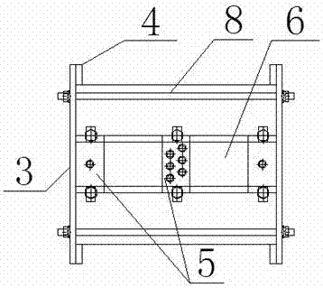
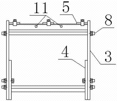
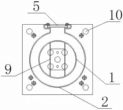
[0026] like figure 1 A horizontal casting mold for high-voltage coils of dry-type transformers is shown, which includes a coil casting inner mold 1, a coil casting outer mold 2, an end positioning and fixing support plate 3, an outer mold lining plate 4, and a terminal fixing plate 5. The inner mold 1 and the coil casting outer mold 2 are cylindrical with two ends open and they are concentric. The coil casting inner mold 1 and the coil casting outer mold 2 are placed horizontally and the two end positioning and fixing support plates 3 enclose the casting mold cavity. , the upper cylinder wall of the coil casting outer mold 2 is provided with a sprue 6, the sprue 6 is connected to the terminal fixing plate 5, and the outer mold lining plate 4 is a plate with an arc-shaped bracket 7, which is arranged on the coil casting outer mold 2 The lower end, the two end positioning fi...


PUM


Abstract

The invention discloses a horizontal casting mold and a casting method for a high-voltage coil of a dry transformer. The horizontal casting mold comprises a coil casting inner mold, a coil casting outer mold, an end positioning and fixing support plate, an outer mold lining plate and a connection terminal fixing plate, wherein the coil casting inner mold and the coil casting outer mold are transversely arranged. The horizontal casting mold is good in air dispersity, so that casting is faster, air bubbles are not easily generated, the local discharge amount of the dry transformer is reduced and the operation reliability of the dry transformer is improved. A coil does not need to be erected, so that the possibility of collapse of the coil is reduced and a product is more reliable in quality and safer; the height of the cast coil can reach the height required by the drawings, and the end part is smooth and does not need to be cut, so that the horizontal casting mold is free of dust pollution and environment-friendly. Due to the small height, capital input of a casting tank can be reduced and the cost is lowered.

Description

technical field [0001] The invention relates to the technical field of dry-type transformers, in particular to a horizontal casting mold for high-voltage coils of dry-type transformers. Background technique [0002] Compared with oil-immersed transformers, dry-type transformers have the advantages of being non-flammable and explosive. Since the advent of dry-type transformers, their capacity has become larger and larger, and the height of the corresponding coils has become higher and higher. The vertical coil casting mold is used for vertical casting through the pouring port on one end of the coil. Due to the small air diffusion area, the casting speed is slow in order to prevent air bubbles. However, there is a defect when casting higher coils. Unfinished, but the epoxy resin for pouring has increased in viscosity, and the resin fluidity is poor, resulting in the problem of easy-to-go air bubbles in pouring; at the same time, vertical casting, there is a risk of line segmen...

Claims


Application Information

Patent Timeline
IPC IPC(8): H01F41/04B29C39/10B29C39/26
CPCB29C39/10B29C39/26H01F41/04
Inventor 刘建萍朱宏李香波韩军张城玮
Owner 山东泰开箱变有限公司
Why Eureka
Try Eureka