
Bus voltage measuring device based on closed end of single phase GIS tank

A bus voltage and measuring device technology, applied in measuring devices, measuring electrical variables, measuring current/voltage, etc., can solve the problems of high insulation requirements, high maintenance and repair costs, and high cost, and achieve high insulation requirements, maintenance and The effect of high maintenance costs

Active Publication Date: 2017-07-07
NORTH CHINA ELECTRIC POWER UNIV (BAODING)
View PDF2 Cites 14 Cited by
  • Summary
  • Abstract
  • Description
  • Claims
  • Application Information

AI Technical Summary

Problems solved by technology

However, there are many problems in monitoring the voltage of high-voltage transmission lines with transformers as the essence. There will be hysteresis and magnetic saturation in the iron core, which will lead to problems such as low measurement linearity, small static and dynamic accuracy ranges, and unsatisfactory transient error characteristics; during the operation of the substation isolation switch, electromagnetic and capacitive transformers prone to failure
Electronic transformers have problems such as the limitation of crystal half-wave voltage, the stability of light sources, the stability of optical device connections, optical transmission loss, and shifts in voltage division ratios, and have major defects in primary sensing structures and electromagnetic shielding. , easily lead to serious measurement errors
In addition, the voltage transformer has common problems such as large transformer size, high cost, high maintenance and overhaul costs, inflexible measurement, large loss, and high insulation requirements.

Method used


Image

  • Bus voltage measuring device based on closed end of single phase GIS tank
  • Bus voltage measuring device based on closed end of single phase GIS tank
  • Bus voltage measuring device based on closed end of single phase GIS tank

Examples


Embodiment Construction

[0026] The following will clearly and completely describe the technical solutions in the embodiments of the present invention with reference to the accompanying drawings in the embodiments of the present invention. Obviously, the described embodiments are only some, not all, embodiments of the present invention. Based on the embodiments of the present invention, all other embodiments obtained by persons of ordinary skill in the art without making creative efforts belong to the protection scope of the present invention.

[0027] The object of the present invention is to provide a busbar voltage measurement device built on the closed end of a single-phase GIS tank body, which can monitor the running state of the high-voltage transmission line in real time.

[0028] In order to make the above objects, features and advantages of the present invention more comprehensible, the present invention will be further described in detail below in conjunction with the accompanying drawings an...


PUM


Abstract

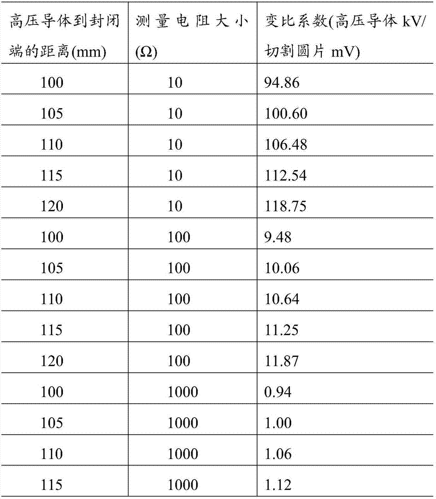
The invention discloses a bus voltage measuring device based on a closed end of a single phase GIS tank. The bus voltage measuring device comprises a metal sensing wafer, a gas insulated combined electrical apparatus, a resistor, a cable, a voltage detector, and a voltage display. The gas insulated combined electrical apparatus comprises a high-voltage conductor with a cylindrical structure and an outer tank body. A part of the closed end of the outer tank body is cut to form the metal sensing wafer, before measuring the voltage, the metal sensing wafer is pasted to the incision of the closed end. One end of the resistor is connected to the metal sensing wafer, and the other end is connected to the closed end. One end of the cable is connected to the resistor, and the other end is connected to the voltage detector. The voltage display is connected to the voltage detector and is used for calculating and displaying the voltage value of the high-voltage conductor to the outer tank body. Therefore, by using the bus voltage measuring device provided by the invention, by measuring the voltage value of the resistor, the voltage value of the high-voltage conductor in the gas insulated combined electrical apparatus to the outer tank body can be calculated, and the purpose of monitoring the running state of a high voltage transmission line is achieved.

Description

technical field [0001] The invention relates to the field of power systems, in particular to a busbar voltage measuring device built at the closed end of a single-phase GIS tank body. Background technique [0002] Safe power transmission, reliable power transmission, and economical power transmission are the current mainstream trends, and driven by this mainstream trend, power transmission technology continues to develop, the scale of the power grid continues to expand, and the voltage level of the power system continues to increase, especially UHV AC and DC Formation and innovation of technology in the field of hybrid power transmission. [0003] At present, my country has successfully developed a 1000kV AC and ±800kV DC hybrid transmission system, prompting my country to enter a new stage of UHV transmission. However, when entering a new stage of UHV power transmission, it also increases the difficulty of real-time monitoring of the operating status of the power system an...

Claims


Application Information

Patent Timeline
Patent Type & Authority Applications(China)
IPC IPC(8): G01R19/00
Inventor 卢斌先孙洪宇
Owner NORTH CHINA ELECTRIC POWER UNIV (BAODING)
Learn More