Eureka AIR delivers breakthrough ideas for toughest innovation challenges, trusted by R&D personnel around the world.

Industrial by-product gypsum calcining equipment

An industrial by-product gypsum and calcination technology, applied in calcium/strontium/barium compounds, inorganic chemistry, chemical instruments and methods, etc., can solve problems such as failure to achieve calcination effects, burnout of drying and calcination machines, and low temperature distribution. To achieve the effect of saving raw materials and energy, reducing output, and commissioning output

Active Publication Date: 2017-07-07
ZHENGZHOU SUNDY BUILDING TECH
View PDF9 Cites 2 Cited by
  • Summary
  • Abstract
  • Description
  • Claims
  • Application Information

AI Technical Summary

Problems solved by technology

[0003] At present, when using dihydrate gypsum to dry to produce hemihydrate gypsum, the gypsum drying and calcining machine is usually used to dry the dihydrate gypsum. The principle is to transport the phosphogypsum to the drying and calcining machine, The internal configuration of the flame-injecting furnace, using the flame ejected from the flame-injecting furnace to generate high-temperature airflow, heats and dries the phosphogypsum, so as to achieve the purpose of gypsum structure conversion. The high spray temperature of the flame-throwing furnace will cause the drying and calcining machine to be burned out. If phosphogypsum is added, the initial temperature in the drying and calcining machine is low and the temperature distribution is uneven, so the calcination effect cannot be achieved. The gypsum is an unqualified product. At present, for unqualified gypsum, it is usually stored in an unqualified gypsum storage tank and treated as waste
However, these unqualified gypsum contains a certain amount of heat and moisture, which are directly treated as waste products, resulting in waste of raw materials, and the natural cooling of the heat inside causes energy loss and consumption

Method used


Image

  • Industrial by-product gypsum calcining equipment
  • Industrial by-product gypsum calcining equipment
  • Industrial by-product gypsum calcining equipment

Examples


Embodiment Construction

[0025] The present invention will be further described in detail below in conjunction with the accompanying drawings.

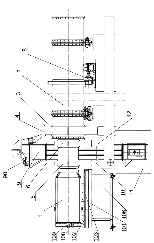
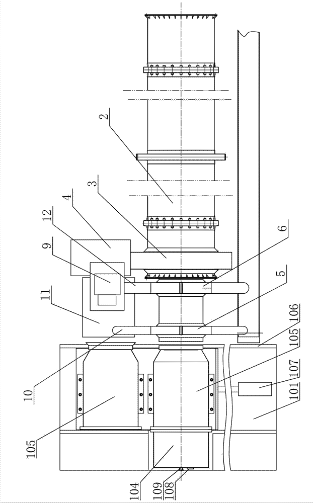
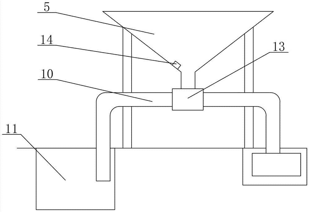
[0026] Such as figure 1 , figure 2 , image 3 , Figure 4As shown, a kind of industrial by-product gypsum calcining equipment comprises flame-breathing furnace 1, kiln head 3, drum 2, feed hopper 4, anhydrous gypsum discharge port 5, hemihydrate gypsum discharge port 6, power transmission device 8 and Waste hoist 9, the front of the drum 2 is provided with a kiln head 3, the kiln head 3 is provided with a feed hopper 4, and the drum 2 at the front of the kiln head 3 is provided with an anhydrous gypsum outlet 5 and the hemihydrate gypsum outlet 6, the anhydrous gypsum outlet 5 and the hemihydrate gypsum outlet 6 are all provided with a temperature sensor 14, the front end of the drum 2 is provided with a flame-throwing furnace 1, and the flame-throwing furnace The hot air outlet 113 of 1 corresponds to the front opening of the drum 2, and the power trans...


PUM


Abstract

The invention relates to industrial by-product gypsum calcining equipment, which comprises a sting-out furnace, a kiln head, a roller, a feed hopper, an anhydrous gypsum discharge hole, a semi-hydrated gypsum discharge hole, a power transmission unit and a waste elevator. According to the invention, a temperature sensor is arranged at the discharge hole of a roller of an existing gypsum drying calcinator, and the discharge hole is also provided with a reversing valve and a discharge pipe. The temperature sensor detects the temperature of a material discharged out of the discharge hole of the roller. When the temperature in the roller is lower than the temperature of qualified gypsum, the temperature sensor controls the reversing valve for reversing, and unqualified gypsum products are conveyed into a waste gypsum storage tank. The waste elevator lifts and conveys unqualified gypsum into the feed hopper of the gypsum drying calcinatory, and then the unqualified gypsum is once again calcined and dried. Therefore, output of unqualified gypsum is reduced, output of qualified gypsum is raised, and raw materials and energy are saved.

Description

technical field [0001] The invention relates to the technical field of industrial by-product gypsum production equipment, in particular to a calcining equipment for industrial by-product gypsum, especially phosphogypsum. Background technique [0002] Gypsum is a chemical composition of calcium sulfate containing crystal water. In daily life, gypsum is divided into natural gypsum and chemical gypsum. Natural gypsum is a mineral containing two crystal water. Chemical gypsum is used when producing fertilizers and other chemical raw materials. The waste produced, with the improvement of the emission requirements of coal-fired boilers, the by-product of the desulfurization process is called desulfurization gypsum; the waste gypsum produced by the production of fertilizers and other phosphides is called phosphogypsum because it contains phosphorus oxide. The application of building materials is mostly to calcinate raw gypsum containing two crystal waters into gypsum containing hal...

Claims


Application Information

Patent Timeline
Patent Type & Authority Applications(China)
IPC IPC(8): C04B11/028
CPCC01F11/466C04B11/028
Inventor 赵嘉珩赵建纲
Owner ZHENGZHOU SUNDY BUILDING TECH
Why Eureka
Eureka Blog
Learn More