Chip corrosion clamp
A fixture and chip technology, applied in the direction of manufacturing tools, workpiece clamping devices, etc., can solve the problems of scratching the LED chip, falling of the LED chip, poor control of the vibration amplitude or frequency, etc., to prevent the chip from falling and scratched effect
- Summary
- Abstract
- Description
- Claims
- Application Information
AI Technical Summary
Problems solved by technology
Method used
Image

Examples
Embodiment 1
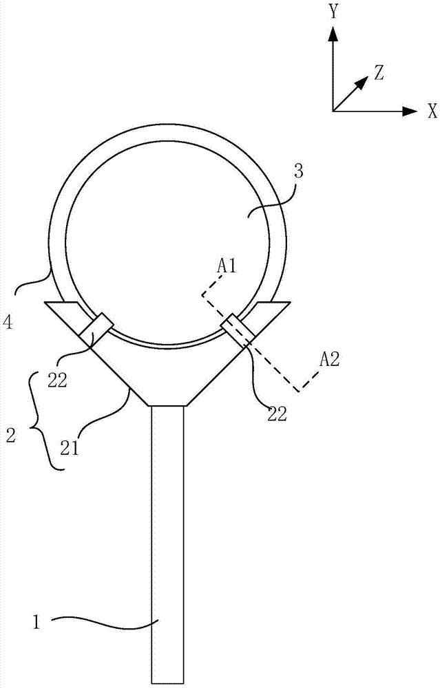
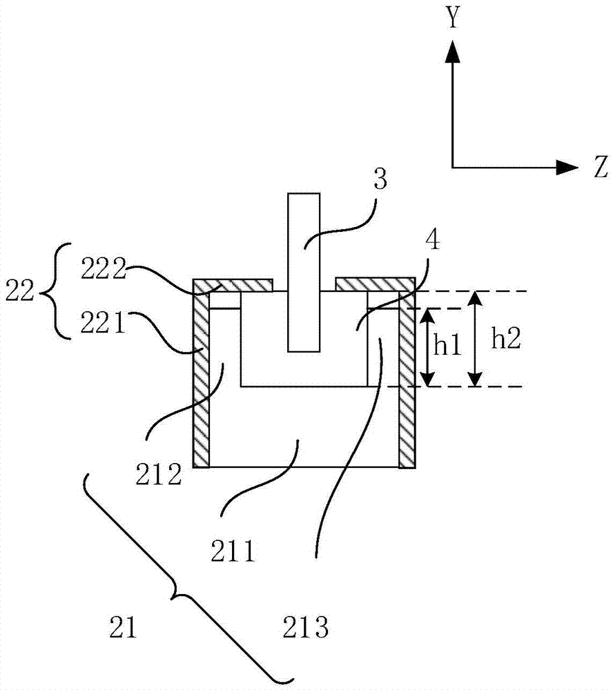
[0032] Figure 1a It is a schematic structural diagram of a chip etching jig clamping a mother-son ring provided in Embodiment 1 of the present invention. Figure 1b for Figure 1a A cross-sectional view of the chip etch fixture along A1-A2 provided in . The chip corrosion fixture includes: a handle 1 and a clamping part 2 connected to the handle 1; the clamping part 2 includes an arc-shaped slot 21 and at least one fixing piece 22 located on the arc-shaped slot 21, the arc-shaped slot 21 cooperates with the fixing member 22 to fix the sub-ring 4 holding the chip 3 .
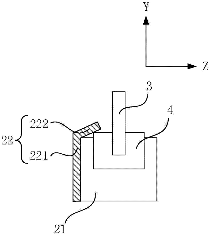
[0033] The shape of fixture 22 has multiple, for example, as Figure 1b As shown, the fixing piece 22 includes a first blocking piece 221 and a second blocking piece 222, and the first blocking piece 221 and the second blocking piece 222 are fixedly connected at a preset angle; Fitting, the second blocking piece 222 bears against the mother and child ring 4, which can effectively limit the movement of the moth...
Embodiment 2
[0040] Figure 2a It is a schematic structural diagram of a state in which a chip etching jig clamps a mother-child ring provided by Embodiment 2 of the present invention, Figure 2b It is a schematic structural diagram of a chip etching jig releasing a mother and son ring state provided by Embodiment 2 of the present invention, Figure 2c for Figure 2aA cross-sectional view of the chip etch fixture along B1-B2 provided in . Compared with the chip etching jig provided in Embodiment 1, the chip etching jig provided in this embodiment further includes an elastic element and a connecting rod in the clamping part, so that the worker can quickly clamp or release the female ring. Specifically, combined with Figure 2a , Figure 2b with Figure 2c As shown, the chip corrosion fixture includes: a handle 1 and a clamping part 2 connected to the handle 1; the clamping part 2 includes an arc-shaped slot 21 and at least one fixing piece 22 located on the arc-shaped slot 21, the arc ...
Embodiment 3
[0046] image 3 It is a schematic structural diagram of a chip etching jig clamping a sub-ring provided by Embodiment 3 of the present invention. Different from the chip etching jig provided in the second embodiment, the clamping part in the chip etching jig provided in this embodiment further includes a pick piece fixed on the connecting rod. Such as image 3 As shown, the chip corrosion fixture includes a handle 1 and a clamping part 2 connected to the handle 1; the clamping part 2 includes an arc-shaped slot 21 and at least one fixing piece 22 located on the side of the arc-shaped slot 21, and the arc-shaped slot The slot 21 cooperates with the fixing part 22 to fix the ring 4 with the chip 3 . The clamping part 2 further includes an elastic element 23 and a connecting rod 24 ; the elastic element 23 is connected to the arc-shaped slot 21 ; one end of the connecting rod 24 is connected to the elastic element 23 , and the other end is connected to the fixing member 22 . I...
PUM
 Abstract
Description
Claims
Application Information
 - R&D
- Intellectual Property
- Life Sciences
- Materials
- Tech Scout
- Unparalleled Data Quality
- Higher Quality Content
- 60% Fewer Hallucinations
Browse by: Latest US Patents, China's latest patents, Technical Efficacy Thesaurus, Application Domain, Technology Topic, Popular Technical Reports.
© 2025 PatSnap. All rights reserved.Legal|Privacy policy|Modern Slavery Act Transparency Statement|Sitemap|About US| Contact US: help@patsnap.com