Automatic sand blasting device

A sandblasting device, an automatic technology, is used in explosion generating devices, used abrasive processing devices, spray guns, etc., and can solve problems such as human harm, inconvenient positioning, and complex clamping.

Pending Publication Date: 2017-07-07
HUAIYIN INSTITUTE OF TECHNOLOGY
View PDF9 Cites 2 Cited by
  • Summary
  • Abstract
  • Description
  • Claims
  • Application Information

AI Technical Summary

Problems solved by technology

[0003] Most of the current sandblasting work is manual sandblasting, which is very harmful to the human body, and the efficiency is not high, and it requires complicated clamping and inconvenient positioning.

Method used


Image

  • Automatic sand blasting device
  • Automatic sand blasting device
  • Automatic sand blasting device

Examples


Embodiment Construction

[0028] The following structural drawings further illustrate the technical solution of the present invention.

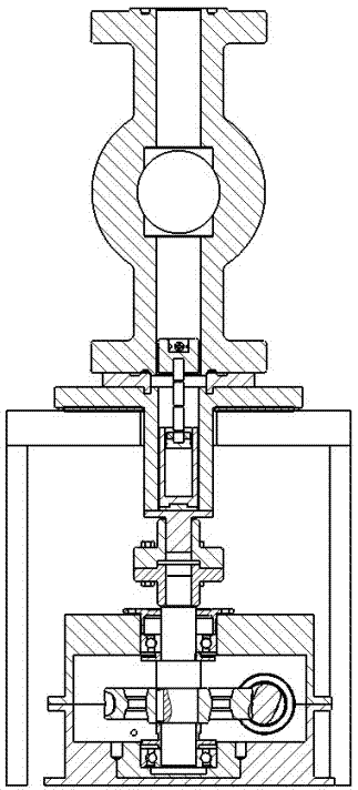
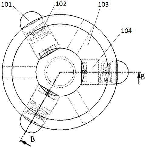
[0029] Such as figure 1 , 2 As shown, the automatic sandblasting device includes a rotating table and a pneumatic sandblasting mechanism that cooperate with each other; the pneumatic sandblasting mechanism is composed of a No. 1 pneumatic cylinder 1, an L-shaped fixed plate 2, a No. , guide rail 5 and sand blaster 6, rollers are installed under the base plate of L-shaped fixed plate 2, guide rail 5 is vertically installed above the base plate of L-shaped fixed plate 2, and the cylinder rod of No. 1 pneumatic cylinder 1 is connected to the L-shaped fixed plate On the side plate of 2, the No. 2 pneumatic cylinder 3 is installed on the side plate of the L-shaped fixed plate 2, and one end of the two connecting rods 4 is installed on the cylinder rod of the No. 2 pneumatic cylinder 3 through the connecting block, and the two connecting rods 4 The other end of the guide ...


PUM


Abstract

The invention discloses an automatic sand blasting device. The automatic sand blasting device comprises a rotating workbench and a pneumatic sand blasting mechanism which are matched with each other. The rotating workbench can rotate a machined part on the rotating workbench. The pneumatic sand blasting mechanism can achieve sand blasting while moving a nozzle up and down, front and back and rotating the nozzle by 90 degrees on the plane according to the position and angle change of the machined part. The automatic sand blasting device is intelligent and self-adaptive, one-time complete sand blasting of the machined part can be completed, the sand blasting efficiency is improved, the labor intensity of workers is relieved, and the phenomenon that the workers work in a severe environment is avoided; and the degree of automation is high, controlling is sensitive and fast, and safety and reliability are high.

Description

technical field [0001] The invention relates to a sand blasting device, in particular to an automatic sand blasting device. Background technique [0002] Valve parts are used in Christmas trees and wellhead devices, and the valve surface needs to have excellent performance. The automatic sandblasting device is a device that automatically completes the sandblasting of valves and other processed parts. It uses compressed air as the power to form a high-speed jet beam, sprays the spray material at high speed on the surface of the workpiece to be processed, and uses the impact of high-speed sand flow to clean it. And roughen the surface of the substrate, so that the outer surface or shape of the workpiece changes. Due to the impact and cutting effect of the abrasive on the surface of the workpiece, the surface of the workpiece can obtain a certain degree of cleanliness and different roughness, so that the performance of the surface of the workpiece can be improved, so the fatig...

Claims


Application Information

Patent Timeline
Patent Type & Authority Applications(China)
IPC IPC(8): B24C1/00B24C3/32B24C5/02B24C9/00
CPCB24C1/00B24C3/32B24C5/02B24C9/00
Inventor 孙全平吴宏亮孙兆伟万仁军韩旭东陈志伟高畅孙权
Owner HUAIYIN INSTITUTE OF TECHNOLOGY
Why Eureka
Try Eureka