
Cervical vertebra rehabilitative instrument

A cervical spine and controller technology applied to a cervical spine rehabilitation device. It can solve problems such as large traction force, insufficient cervical support, and excessive support area, and achieve the effects of reducing weight, easy to wear, and reducing volume

Pending Publication Date: 2017-07-07
GUANGDONG POLYTECHNIC OF IND & COMMERCE
View PDF20 Cites 9 Cited by
  • Summary
  • Abstract
  • Description
  • Claims
  • Application Information

AI Technical Summary

Problems solved by technology

[0002] The existing cervical spine rehabilitation collar, whose products are mainly supported by hard rubber, also has certain problems in the protection of the cervical spine: 1, the cervical spine is easily damaged due to insufficient protection of the hard support; 2, the cervical spine is not supported in place, and each support point is not Can achieve close fit, lack of sufficient power to stabilize the cervical spine and longitudinal tension can not achieve the effect of protection and treatment
[0003] In response to this problem, the "Full-automatic Dynamic Stable Cervical Vertebral Rehabilitation Device" of Patent No. zl201020666402 proposed the concept of automatic control, which can also be seen as a portable rehabilitator in its description, but because it directly gives the cervical spine its related parts through the airbag Support, there is the fact that the traction force on the human cervical spine cannot be accurately calculated - there is no way to achieve real intelligent control, and there is a risk of excessive traction due to the excessive support area of ​​some users, which in turn damages the cervical spine
[0004] There are two major disadvantages in the above scheme: one cannot truly realize intelligent control, and neither doctors nor patients can really understand the actual situation of the traction force of the cervical spine; the other, because the inability to correctly judge the magnitude of the traction force, it is easy to cause the danger of cervical spine injury
Therefore, the practical requirements cannot be met

Method used


Image

  • Cervical vertebra rehabilitative instrument
  • Cervical vertebra rehabilitative instrument

Examples


Embodiment Construction

[0024] The following will clearly and completely describe the technical solutions in the embodiments of the present invention with reference to the accompanying drawings in the embodiments of the present invention. Obviously, the described embodiments are only some, not all, embodiments of the present invention. Based on the embodiments of the present invention, all other embodiments obtained by persons of ordinary skill in the art without creative efforts fall within the protection scope of the present invention.

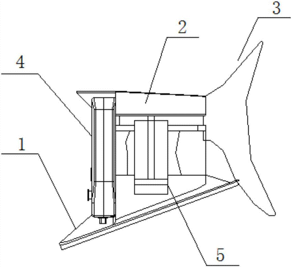
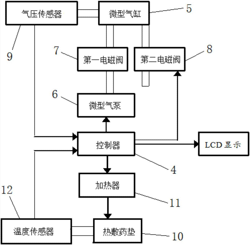
[0025] see figure 1 and figure 2 Shown, the preferred embodiment of the present invention, a kind of cervical spine rehabilitation device, it comprises shoulder rest 1, neck front support 2, neck rear support 3, miniature air pump 6, controller 4 and two miniature air cylinders 5, two described The cylinder block of miniature cylinder 5 is connected with the left and right sides of described shoulder support 1 respectively, and the push rod of two described minia...


PUM


Abstract

The invention provides a cervical vertebra rehabilitative instrument. The cervical vertebra rehabilitative instrument comprises a shoulder support, an anterior cervical support, a posterior cervical support, a mini air pump, a controller and two mini cylinders, wherein cylinder bodies of the two mini cylinders are connected with the left side and the right side of the shoulder support respectively, push rods of the two mini cylinders are connected with the left side and the right side of the anterior cervical support respectively, the rear side of the anterior cervical support is connected with the posterior cervical support through a rigid hinge, the controller and the mini air pump are both fixed on the front side of the shoulder support, the controller is electrically connected with the mini air pump, and the mini air pump is connected with the two mini cylinders. The cervical vertebra rehabilitative instrument has the advantages of being intelligent, controllable, convenient to carry and capable of achieving overall traction of the mandible and the occipital bone, so as to provide reliable data for doctors in cervical vertebra treatment and study and provide convenience and mental dependence for patients in use.

Description

technical field [0001] The invention relates to a medical rehabilitation device, in particular to a cervical spine rehabilitation device. Background technique [0002] The existing cervical spine rehabilitation collar, whose products are mainly supported by hard rubber, also has certain problems in the protection of the cervical spine: 1, the cervical spine is easily damaged due to insufficient protection of the hard support; 2, the cervical spine is not supported in place, and each support point is not Can achieve close fit, lack of sufficient power to stabilize the cervical spine and longitudinal tension can not achieve the effect of protection and treatment. [0003] In response to this problem, the "Full-automatic Dynamic Stable Cervical Vertebral Rehabilitation Device" of Patent No. zl201020666402 proposed the concept of automatic control, which can also be seen as a portable rehabilitator in its description, but because it directly gives the cervical spine its related ...

Claims


Application Information

Patent Timeline
Patent Type & Authority Applications(China)
IPC IPC(8): A61F7/02A61F5/042A61M37/00
CPCA61M37/00A61F5/0102A61F5/042A61F7/02A61F2007/0203A61F2007/0095A61F2007/0226A61F2007/0011A61F2007/0295A61F2007/0261A61M2037/0007A61M2205/36
Inventor 徐勇军邱腾雄丘永亮王若纯林俊强
Owner GUANGDONG POLYTECHNIC OF IND & COMMERCE
Learn More