
Magnetic resonance system and imaging method thereof

A magnetic resonance and imaging technology, applied in the direction of measuring magnetic variables, measuring devices, instruments, etc., can solve the problems of reducing fill factor, increasing coil loss, and time-consuming adjustment process, so as to improve uniformity and contrast and ensure consistency performance and accuracy, avoiding the effect of excessive absorption rate of radio frequency energy

Active Publication Date: 2017-07-04
SHANGHAI UNITED IMAGING HEALTHCARE
View PDF13 Cites 16 Cited by
  • Summary
  • Abstract
  • Description
  • Claims
  • Application Information

AI Technical Summary

Problems solved by technology

where enlarging the coil geometry increases the B 1 While improving the uniformity of the field, it will increase the coil loss and reduce the fill factor, and because the amount of tissue contained in the coil increases, it will also form an additional noise source, although B 1 The enhancement of field uniformity is accompanied by the reduction of Signal Noise Ratio (S / N); the multi-channel parallel transmission technology is mainly based on the B of all single transmission channels. 1 Field adjustment of the amplitude and phase optimization of each channel B 1 The uniformity of the field, however, the adjustment process is time-consuming, and it is difficult to meet the requirements of pre-scanning system calibration before clinical sequence scanning
In addition, in order to make the transmitted RF pulses reach the required flip angle in the MRI system, the RF transmission power of the body coil needs to be calibrated before scanning. The unevenness of the high-field RF excitation field makes the voltage obtained by the traditional calibration method The value can only represent the average level of the excitation area, and cannot be used for B under high field 1 field uniformity issues

Method used


Image

  • Magnetic resonance system and imaging method thereof
  • Magnetic resonance system and imaging method thereof
  • Magnetic resonance system and imaging method thereof

Examples


Embodiment Construction

[0040] In order to make the above objects, features and advantages of the present invention more obvious and comprehensible, specific implementations of the present invention will be described in detail below in conjunction with the accompanying drawings and embodiments.

[0041] The magnetic resonance system mainly includes a scanning control system, a gradient system, a radio frequency system and a superconducting magnet, wherein the superconducting magnet, the gradient system and the radio frequency system are arranged around the scanning cavity, and the superconducting magnet generates uniform and stable Static magnetic field B 0 The main magnetic field, the intensity uniformity of the main magnetic field, the size of the scanning cavity, etc. will affect the signal-to-noise ratio and image resolution of the magnetic resonance signal; the gradient system consists of gradient coils, gradient controllers, digital-to-analog converters, gradient amplifiers and gradient cooling ...


PUM


Abstract

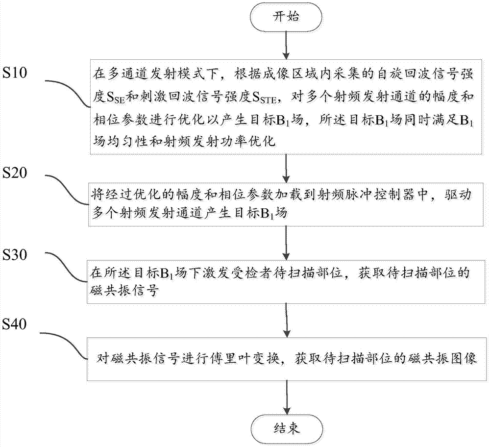
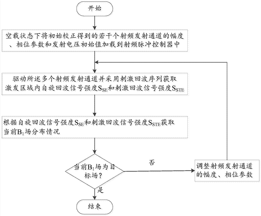
The invention discloses a magnetic resonance system imaging method, which comprises the following steps: under a multichannel emission mode, according to spin echo signal intensity SSE and stimulated echo signal intensity SSTE, carrying out optimization on amplitude and phase parameters of a plurality of radio frequency emission channels to generate a target B1 field, wherein the target B1 field meets B1 field uniformity and radio frequency emission power optimization simultaneously; loading the optimized amplitude and phase parameters to a radio frequency pulse controller, and driving the plurality of radio frequency emission channels to generate the target B1 field; under the target B1 field, exciting a part to be scanned of a subject to obtain a magnetic resonance signal of the part to be scanned; and carrying out Fourier transform on the magnetic resonance signal to obtain a magnetic resonance image of the part to be scanned. The spin echo signal intensity and the stimulated echo signal intensity are collected to reflect distribution of the B1 field; and fast correction can be carried out to obtain a uniform B1 field, and radio frequency emission power can be corrected. The invention also provides a magnetic resonance system.

Description

【Technical field】 [0001] The invention relates to the technical field of magnetic resonance imaging, in particular to technologies related to radio frequency field optimization. 【Background technique】 [0002] Magnetic resonance imaging (Magnetic Resonance Imaging, MRI) technology is a non-invasive detection technology produced with the development of computer technology, electronic circuit technology, and superconductor technology. It is extremely important in today's clinical diagnosis and medical research. meaning. The basic process of magnetic resonance imaging is: the transmitting unit generates a radio frequency field perpendicular to the main magnetic field of the scanning device, and the radio frequency pulse energy makes the resonant nucleus spin in the human body. At this time, the human body is equivalent to a receiver and is accurately tuned to the resonance frequency After the radio frequency pulse stops, the protons in the irradiated part of the human body gra...

Claims


Application Information

Patent Timeline
IPC IPC(8): G01R33/387
CPCG01R33/387
Inventor 蒋瑞瑞
Owner SHANGHAI UNITED IMAGING HEALTHCARE
Learn More