
Tunnel furnace and workpiece thermal treatment process

A tunnel furnace and workpiece technology, applied in heat treatment furnaces, heat treatment equipment, heat treatment process control, etc., can solve problems such as increasing labor costs, affecting the effect of heat treatment of workpieces, and increasing the probability of work-related accidents.

Pending Publication Date: 2017-06-27
上海迅美工业设备有限公司
View PDF8 Cites 7 Cited by
  • Summary
  • Abstract
  • Description
  • Claims
  • Application Information

AI Technical Summary

Problems solved by technology

[0002] Heat treatment refers to a processing technology in which the material is heated, kept warm and cooled in a solid state to obtain the desired structure and performance; the existing workpiece heat treatment process mainly consists of workers placing the workpiece in a heating device and heating it to a specified temperature. , and then placed in the heat preservation device for heat preservation. When the heat preservation time is reached, the worker puts the workpiece into the cooling device for cooling. The heat treatment of the workpiece is done manually, which greatly improves the cost of employment, and Increase the probability of industrial accidents; at the same time, because the workpiece is in contact with the outside air several times during the heat treatment process, it will greatly affect the effect of the heat treatment of the workpiece

Method used


Image

  • Tunnel furnace and workpiece thermal treatment process
  • Tunnel furnace and workpiece thermal treatment process
  • Tunnel furnace and workpiece thermal treatment process

Examples


Embodiment Construction

[0082] The specific implementation manners of the present invention will be further described below in conjunction with the drawings and examples. The following examples are only used to illustrate the technical solution of the present invention more clearly, but not to limit the protection scope of the present invention.

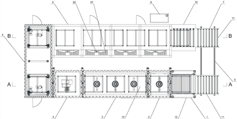
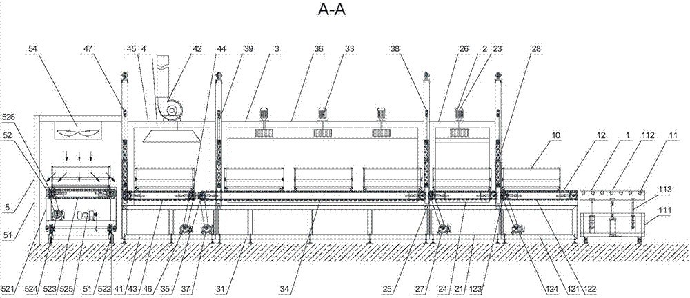
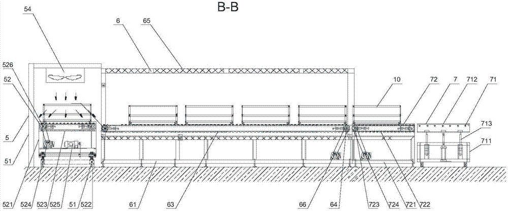
[0083] Such as Figure 1-6 Shown, the present invention is a kind of tunnel furnace, comprising:

[0084] The feeding part 1 is used to receive the workpiece 10;

[0085] The preheating part 2 is connected with the feeding part 1, and is used for preheating the workpiece 10;

[0086] The constant temperature part 3 is connected with the preheating part 2, and is used for constant temperature heating of the workpiece 10;

[0087] The heat preservation part 4 is connected with the constant temperature part 3, and is used for heat preservation of the workpiece 10;

[0088] The quenching part 5 is connected with the transition part, and is used for rapidly ...


PUM


Abstract

The invention discloses a tunnel furnace and a workpiece thermal treatment process. The tunnel furnace comprises a feeding portion for receiving a workpiece, a preheating portion connected with the feeding portion and used for preheating the workpiece, a constant-temperature portion connected with the preheating portion and used for heating the workpiece at the constant temperature, a heat insulation portion connected with the constant temperature portion and used for keeping the temperature of the workpiece, a shock cooling portion connected with a transition portion and used for quickly cooling the workpiece, a cooling portion connected with the shock cooling portion and used for continuously cooling the workpiece and a discharging portion connected with the cooling portion and used for receiving the workpiece. The tunnel furnace and the workpiece thermal treatment process have the beneficial effects that the automatic level of the workpiece thermal treatment and the workpiece thermal treatment effect are improved, the labor is reduced, and accordingly the production cost of enterprises and the occupational injury rate generated in the production process are lowered; and meanwhile, the situation that the workpiece is in contact with the external air in the thermal treatment process is avoided by means of the tunnel furnace, so that the thermal treatment effect of the workpiece is guaranteed greatly, the heating uniformity and the heating effect of the workpiece are improved, and the cooling and shaping effect of the workpiece is improved.

Description

technical field [0001] The invention relates to the field of mechanical processing, in particular to a tunnel furnace and a workpiece heat treatment process. Background technique [0002] Heat treatment refers to a processing technology in which the material is heated, kept warm and cooled in a solid state to obtain the desired structure and performance; the existing workpiece heat treatment process mainly consists of workers placing the workpiece in a heating device and heating it to a specified temperature. , and then placed in the heat preservation device for heat preservation. When the heat preservation time is reached, the worker puts the workpiece into the cooling device for cooling. The heat treatment of the workpiece is done manually, which greatly improves the cost of employment, and The probability of industrial accidents is increased; at the same time, since the workpiece is exposed to the outside air several times during the heat treatment process, the effect of ...

Claims


Application Information

Patent Timeline
Patent Type & Authority Applications(China)
IPC IPC(8): C21D1/00C21D9/00C21D11/00
CPCC21D1/00C21D9/005C21D9/0062C21D11/00
Inventor 刘寿贤
Owner 上海迅美工业设备有限公司
Learn More