


Quick Research
Generate reliable direction feasibility study reports for your R&D in just a few steps.

Technical Q&A
Discover and master advanced knowledge NOW. Basics, ideas, possibilities, all at once.

Find Solutions
As an expert in R&D theories, this can generate solutions to your technical problems instantly.

Evaluate Feasibility
Analyze your overall solution with one click, know your potential R&D risks in advance.

Monitor Landscape
Get weekly tech updates, stay abreast of the latest tech innovations and key insights.
Controller, chip and method for eliminating current ripples of LED (Light-Emitting Diode) driving system
A technology of LED drive and system current, which is applied in the direction of electric light source, electrical components, circuit layout, etc., can solve the problems of eliminating ripple and cannot be realized, and achieve the effect of eliminating current ripple, improving work efficiency and increasing time constant
- Summary
- Abstract
- Description
- Claims
- Application Information
AI Technical Summary
Problems solved by technology
Method used
Image

Examples
Embodiment 1
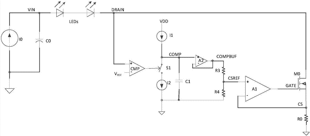
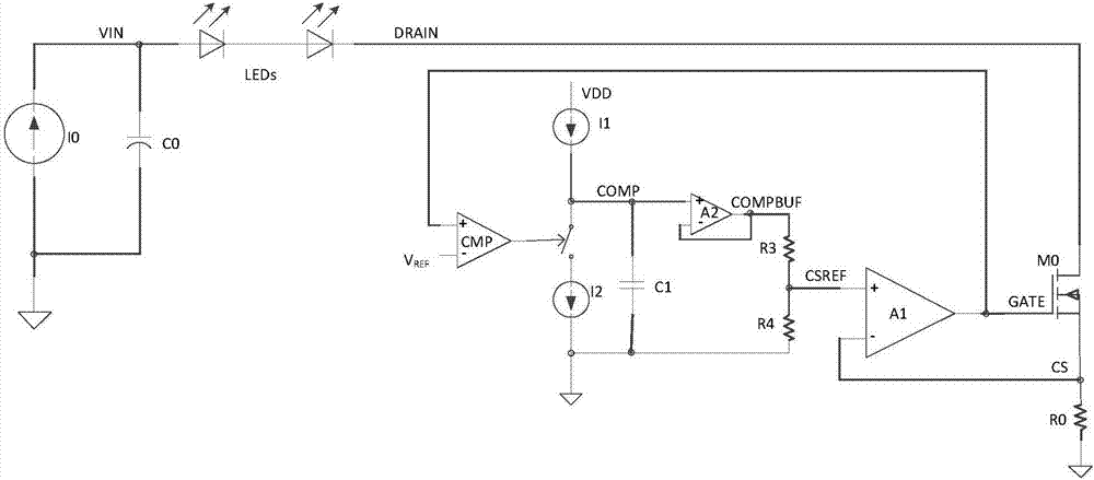
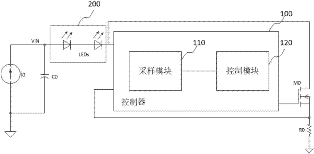
[0045] This embodiment discloses a controller for eliminating current ripple in an LED driving system. The following uses a MOS tube as an example for illustration. In other implementations, the power tube may also be a triode or other types of power tubes. Such as image 3 As shown, the controller 100 is electrically connected to the output terminal of the LED load 200 and the first sampling resistor R0. The controller 100 is used to sample the voltage V at the output terminal of the LED load 200 DRAIN and the voltage V across the first sampling resistor R0 CS , and, according to the voltage V at the output terminal of the LED load 200 DRAIN and the voltage V across the first sampling resistor R0 CS generate the first voltage signal V DV1 ; Further, the controller 100 also according to the first voltage signal V DV1 and the first voltage signal V DV1 generate the corresponding control signal V GATE , through the control signal V GATE Control the conduction state of th...
Embodiment 2
[0062] This embodiment discloses a method for eliminating current ripple in an LED drive system, which uses the controller disclosed in Embodiment 1:
[0063] First, the controller adopts the voltage V of the output terminal of the LED load 200 DRAIN and the voltage V across the first sampling resistor R0 CS , and according to the voltage V at the output of the LED load 200 DRAIN and the voltage V across the first sampling resistor R0 CS generate the first voltage signal V DV1 ; The controller then according to the first voltage signal V DV1 and the voltage across the first sampling resistor V CS Generate control signal V GATE , so as to control the conduction state of the power transistor M0 connected to the LED load 200, so that the first voltage signal V DV1 The magnitude of the voltage and the reference voltage V REF are equal, the elimination of the current ripple of the LED load 200 is realized.
[0064] Specifically, the sampling module 110 samples the output te...
PUM
 Abstract
Description
Claims
Application Information
 - R&D Engineer
- R&D Manager
- IP Professional
- Industry Leading Data Capabilities
- Powerful AI technology
- Patent DNA Extraction
Browse by: Latest US Patents, China's latest patents, Technical Efficacy Thesaurus, Application Domain, Technology Topic, Popular Technical Reports.
© 2024 PatSnap. All rights reserved.Legal|Privacy policy|Modern Slavery Act Transparency Statement|Sitemap|About US| Contact US: help@patsnap.com