Motor torque control device and torque control system

A torque control and motor technology, applied in the field of torque control devices and torque control systems, can solve problems such as complexity, deterioration of torque accuracy, large parameter errors, etc., and achieve the effect of high-precision torque control and simple methods

Active Publication Date: 2021-10-22
SANKEN ELECTRIC CO LTD
View PDF5 Cites 0 Cited by
  • Summary
  • Abstract
  • Description
  • Claims
  • Application Information

AI Technical Summary

Problems solved by technology

[0008] The inventors of the present application found that in the existing torque control device, since parameters such as magnetic flux and secondary resistance value that cannot be directly measured are used, there is a problem that the error of the parameters is large. As a result, the control of the torque In addition, due to the improvement of automatic tuning technology, the detection accuracy of the parameters of the induction motor will be improved, but the secondary resistance value of the induction motor will change after the winding temperature rises, so in the case of continuing to use the motor, there is a problem with the The problem that the torque accuracy gradually deteriorates at the beginning of operation; in addition, the control device of the above-mentioned Patent Document 1 is relatively complicated, and a simpler and more accurate torque control device is desired

Method used


Image

  • Motor torque control device and torque control system
  • Motor torque control device and torque control system
  • Motor torque control device and torque control system

Examples


Embodiment 1

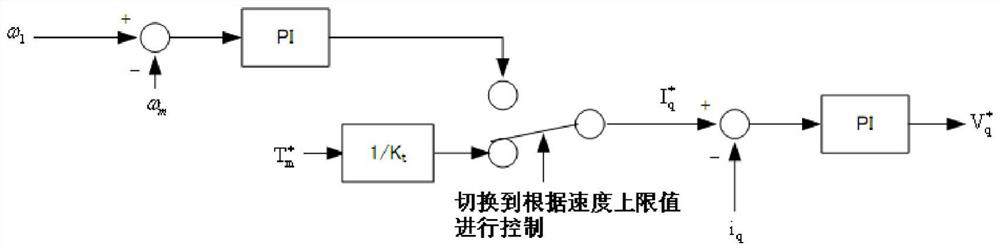
[0031] In this application, the first embodiment provides a torque control device of an electric motor, which outputs a Q-axis current command value for torque control of the sensing motor, which is used to generate three-phase voltage values. with And, the three-phase voltage value with Control the inverter portion outputs an output current I for driving the motor u I v And i w . In this embodiment, a three-phase voltage command value is generated. with And make the inverter unit generate output current I u I v And i w A method of rotating the motor can be referred to in the prior art, and the present embodiment will not be described later.

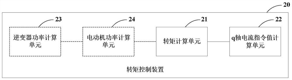
[0032]figure 2 It is a constituent diagram of the torque control device of the present embodiment, such as figure 2 As shown, the torque control device 20 can include a torque calculating unit 21 and a Q-axis current command value calculation unit 22, wherein:

[0033] The torque calculation unit 21 is based on the rotational speed of ...

Embodiment 2

[0064] The present application is provided with a torque control system of an electric motor for torque control of the motor. The torque control system includes a torque control device according to Embodiment 1.

[0065] Figure 5 It is a schematic diagram of the torque control system of the present embodiment, such as Figure 5 As shown, the torque control system 500 includes a torque control device 501, a three-phase voltage calculation unit 502, an inverter portion 503, and a feedback signal generating unit 504. in:

[0066] Torque control device 501 is used to generate a Q-axis current command value Three-phase voltage calculation unit 502 based on Q-axis current command value D axis current command value Q-axis current feedback value I q And D-axis current feedback value i d , Calculate three-phase voltage value with The inverter portion 503 is in three-phase voltage value with Under the control, DC power is converted into an output current I for driving the motor 106. ...


PUM


Abstract

Embodiments of the present application provide a torque control device and a torque control system for a motor, the torque control device includes: a torque calculation unit, which calculates the torque of the motor according to the rotation speed and output power of the motor; and A q-axis current command value calculation unit that calculates a q-axis current command value based on a torque command and the torque calculated by the torque calculation unit. According to the application, torque control can be carried out with high precision during operation of the electric motor independently of the parameters of the induction motor and in a simple manner.

Description

Technical field [0001] The present application relates to the field of electromechanical, and more particularly to a torque control device and a torque control system of an electric motor. Background technique [0002] When the motor is running, it is necessary to torque control of the motor, that is, according to the torque command, generate current command and voltage command for controlling the operation of the motor, these current commands and voltage commands are further calculated to control the inverter generation. The output current used to drive the motor. [0003] figure 1 A schematic diagram of the prior art torque control device, such as figure 1 As shown, in the existing torque control device, torque command Multiply the torque coefficients calculated according to the parameters of the induction motor t Recall 1 / k t To get Q-axis current command values Calculate the feedback signal I of the Q-axis current q Q-axis current command value Deviation, and proportion...

Claims


Application Information

Patent Timeline
Patent Type & Authority Patents(China)
IPC IPC(8): H02P21/20H02P27/08
CPCH02P27/08
Inventor 中岛洋一郎
Owner SANKEN ELECTRIC CO LTD
Why Eureka
Try Eureka