
Modular multi-level converter inter-phase power unbalance control method

A modular multi-level, power unbalanced technology, applied in the direction of reducing the asymmetry of the multi-phase network, eliminating/reducing the asymmetry of the multi-phase network, converting the AC power input to the DC power output, etc., can solve the three-phase power imbalance. Problems such as balance, unbalanced three-phase power of battery panels, unbalanced output power of AC grid, etc.

Active Publication Date: 2017-06-20
HEFEI UNIV OF TECH
View PDF2 Cites 21 Cited by
  • Summary
  • Abstract
  • Description
  • Claims
  • Application Information

AI Technical Summary

Problems solved by technology

[0009] Literature "Power Balance Control Scheme of Cascaded H-Bridge Multilevel Inverter for Grid-Connection Photovoltaic Systems" Fusheng Wang, Le Yang, WangMao, Yu Shineng and Xing Zhang. [C] 2016IEEE 8th International Power Electronics and Motion Control Conference (IPEMC-ECCE Asia) :pp1530-1545, 22-26May 2016HefeiAnHui China (“Power unbalance control strategy for cascaded H-bridge multi-level photovoltaic grid-connected inverter”, 2016 IEEE 8th International Conference on Power Electronics and Drive Control, 1530~ 1545 pages, May 22-26, 2016, Hefei, Anhui, China) and the literature "Modular cascaded H-bridge multilevel PV inverter with distributed MPPT forgrid-connected applications," Bailu Xiao, Lijun Hang, Jun Mei, Cameron Riley, LeonM.Tolbert , and Burak Ozpineci, IEEE Trans.Ind.Appl., vol.51, no.2, MARCH / APRIL2015, pp1722-1731 ("Modular cascaded H-bridge multilevel photovoltaic inverter with distributed MPPT function and Network application", "IEEE Journal-Industrial Application Journal", 2015, Vol. 51, No. 2, pp. 1722-1731) proposed a distributed power unbalance control method for cascaded H-bridge inverter sub-modules with photovoltaic panels , the core idea is to inject zero-sequence components into the three-phase AC voltage to ensure the symmetrical output of the three-phase AC grid current and achieve the purpose of unbalanced output of three-phase power, but the control capability of the scheme is limited by the modulation degree, and the topology, Only the sub-module battery board side to the three-phase AC grid side, there is no public DC grid side, and cannot participate in the control of the DC grid, which is different from the proposed three-terminal control
[0010] Literature "Multi-objective Power Management Strategy for MMC-Based EV FleetIntegrated into Smart Grid", Meiqin Mao, Tinghuan Tao, Yong Ding, Liuchen Chang, Nikos Hatziargyriou, [C] 2016IEEE 8th International Power Electronics and Motion Control Conference (IPEMC-ECCE Asia ):pp2863-2869, 22-26May 2016HefeiAnHui China("MMC-Multi-objective Power Management Strategy Based on Electric Vehicle Group Integration into Microgrid", 2016 IEEE 8th International Conference on Power Electronics and Drive Control, 2863-2869 Page, May 22-26, 2016, Hefei, Anhui, China) adopts the MMC topology, and the bridge arm sub-module adopts the hybrid cascade connection of the energy storage battery and the full-bridge module, and the electric vehicle and the half-bridge module, but the article only introduces the same bridge The strategy of charging and discharging modulation of multiple sub-modules of the arm does not involve the power unbalance control between three phases
[0011] It can be seen from the above existing technologies that firstly, the existing literature does not consider the power control of the DC grid. Secondly, when considering the three-phase power imbalance problem of the battery board connected to the sub-module, the solution needs to be achieved by injecting zero-sequence voltage into the AC grid. In this way, the output power of the AC grid is unbalanced, and then the unbalanced output of three-phase power is realized, but its control ability will be limited by the modulation degree and other conditions.

Method used


Image

  • Modular multi-level converter inter-phase power unbalance control method
  • Modular multi-level converter inter-phase power unbalance control method
  • Modular multi-level converter inter-phase power unbalance control method

Examples


Embodiment Construction

[0119] The preferred modes of the present invention will be further described in detail below in conjunction with the accompanying drawings.

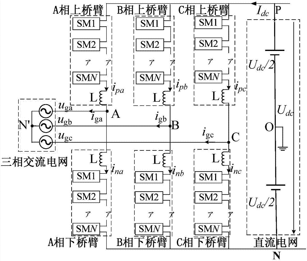
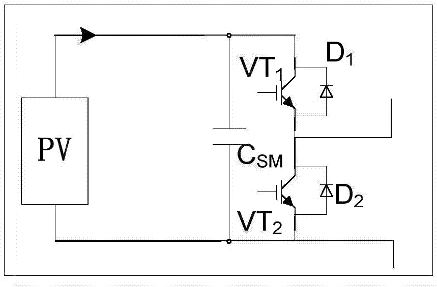
[0120] A method for controlling power imbalance between phases of a modular multilevel converter. The modular multilevel converter of the present invention includes ABC three-phases, each phase is divided into an upper bridge arm and a lower bridge arm, and each bridge The arm is composed of N sub-modules with photovoltaic cells and an inductor L, the i-th sub-module of the bridge arm is denoted as SMi, i=1, 2, 3···N, where N>1, that is, the Each phase of the modular multilevel converter contains 2N sub-modules; the modular multi-level converter system contains a common DC bus, connected to the DC grid; each sub-module consists of a half-bridge sub-module, a supporting capacitor C SM and a group of photovoltaic cells in parallel; the output voltage of each sub-module is 0V or the voltage of the photovoltaic cell; the half-bridge sub-mod...


PUM


Abstract

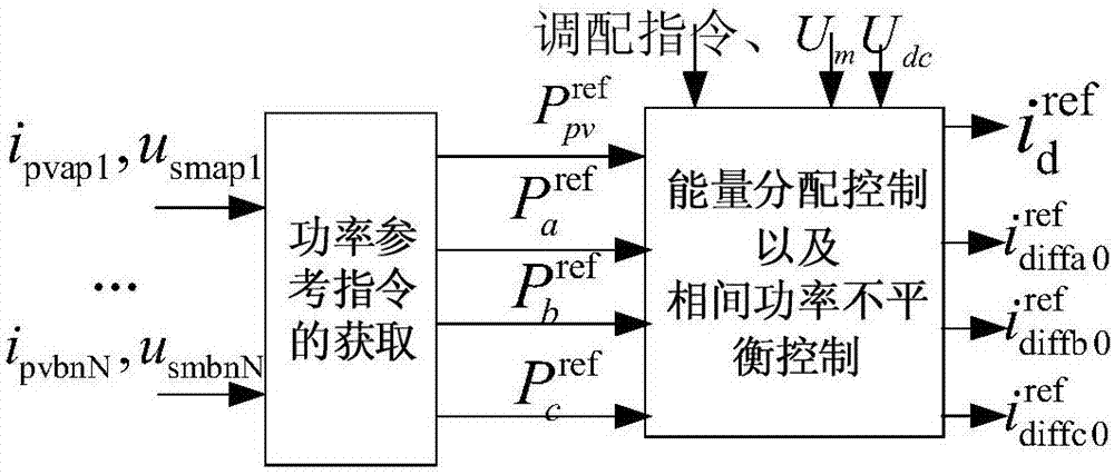
The invention discloses a modular multi-level converter inter-phase power unbalance control method. A modular multi-level converter (MMC) system comprises three ends, that is, submodules having photovoltaic cell panels respectively, a DC power grid and a three-phase AC power grid. The control method comprises the following steps: obtaining output power of each submodule; carrying out three-end power control according to a system power allocation instruction; and when output power instructions of the three-phase cell panels are not equal, carrying out power tracking by injecting bridge arm zero-sequence ring current into each phase of bridge arm according to unbalance conditions, so that a three-phase system is allowed to operate stably according to a preset power instruction and balance of output power of the three-phase AC power grid is ensured.

Description

technical field [0001] The invention relates to a method for controlling unbalanced power between phases of a modularized multilevel converter, in particular to a method for controlling unbalanced power between phases when a sub-module is an active module in an MMC topology. Background technique [0002] Modular Multilevel Converter (MMC) was first proposed by scholars such as R.Marquardt in Germany. The bridge arm of this topology adopts a cascaded structure of half-bridge sub-modules, which avoids direct series connection of a large number of switching devices and obtains multi-level output characteristics. Compared with the commonly used diode neutral point clamped (Neutral Point Clamped, NPC) multilevel converter and flying capacitor (Flying Capacitor, FC) multilevel converter, MMC has the following advantages: [0003] (1) Modular structure is adopted, without adding clamping diodes or flying capacitors; [0004] (2) The voltage borne by a single sub-module is relativ...

Claims


Application Information

Patent Timeline
IPC IPC(8): H02J3/26H02J3/38H02M7/483H02M7/521
CPCH02J3/26H02J3/385H02M7/483H02M7/521Y02E10/56Y02E40/50
Inventor 张兴刘萍王付胜刘芳刘亮吕祎林
Owner HEFEI UNIV OF TECH
Learn More